Mitsubishi Galant 9G. Manual - part 307


  Index      Mitsubishi     Mitsubishi Galant 9G - service repair manual


Search            


Content   ..  305  306  307  308   ..


Mitsubishi Galant 9G. Manual - part 307


AUTO A/C DIAGNOSIS

TSB Revision

AUTOMATIC AIR CONDITIONING

55B-14

NOTE: Also check joint connector C-03 for loose, corroded, or 
damaged terminals, or terminals pushed back in the connector. 
If joint connector C-03 is damaged, repair or replace the con-
nector as described in GROUP 00E, Harness Connector 
Inspection 

P.00E-2

.

Q: Are the wiring harnesses between A/C-ECU connector 

C-15 (terminals 20), C-16 (terminals 22) and interior 
temperature sensor connector C-123 (terminals 1 and 2) 
in good condition?
YES : 
Go to Step 6.
NO :  Repair the wiring harness. Then go to Step 7.

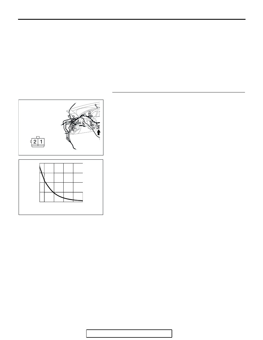
STEP 6. Check the interior temperature sensor.
(1) Disconnect interior temperature sensor connector C-123.

(2) When the resistance between the sensor terminals is 

measured under two or more temperature conditions, the 
resistance should approximately satisfy the illustrated 
values.
NOTE: The temperature conditions when checking should 
not exceed the range shown in the diagram.

Q: Is the interior temperature sensor in good condition?

YES : Replace the A/C-ECU. Then go to Step 7.
NO :  Replace the interior temperature sensor. Then go to 

Step 7.

AC305231CK

CONNECTOR: C-123

HARNESS SIDE

AC103488 AC

RESISTANCE
   (k

)

TEMPERATURE ˚C (˚F)

20

15

10

5

0

0

20

40

60

80

-10

(32) (68) (104) (140) (176)

(14)

AUTO A/C DIAGNOSIS

TSB Revision

AUTOMATIC AIR CONDITIONING

55B-15

STEP 7. Recheck for diagnostic trouble code.
Check again if the DTC is set.
(1) Connect scan tool MB991958 to the data link connector
(2) Turn the ignition switch to the "ON" position.
(3) Check if the DTC is set.
(4) Turn the ignition switch to the "LOCK" (OFF) position.
Q: Is the check result satisfactory?

YES : The procedure is complete.
NO :  Return to Step 1.

AC305412

AB

MB991910

DATA LINK

CONNECTOR

MB991824

MB991827

AUTO A/C DIAGNOSIS

TSB Revision

AUTOMATIC AIR CONDITIONING

55B-16

SYMPTOM CHART

M1554005000203

CAUTION

During diagnosis, a DTC code associated with 
another system may be set when the ignition 
switch is turned on with connector(s) discon-
nected. On completion, confirm all systems for 
DTC code(s). If DTC code(s) are set, erase them 
all.

SYMPTOM

INSPECTION 
PROCEDURE NO.

REFERENCE 
PAGE

When the ignition switch is "ON", the A/C does not operate.

1

REFER TO GROUP 
55A 

− SYMPTOM 

CHART 

P.55A-178

When the air outlet changeover control knob is moved to 
DEFROSTER or DEFROSTER/FOOT position, the A/C or the 
inside/outside air changeover damper motor does not operate.

2

Outside/Inside air changeover is not possible.

3

When the A/C is operating, temperature inside the passenger 
compartment does not decrease (cool air is not emitted).

4

Front blower fan and motor do not turn.

5

Front blower air amount cannot be changed.

6

The A/C indicator flashes.

7

Defogger function does not operate.

8

Defogger timer function does not operate.

9

Malfunction of the A/C-ECU power supply system.

10

Condenser fan does not operate.

11

REFER TO GROUP 
14 

− SYMPTOM 

CHART 

P.14-3

When sunlight intensity changes, air outlet temperature does 
not change.

12

P.55B-17

AUTO A/C DIAGNOSIS

TSB Revision

AUTOMATIC AIR CONDITIONING

55B-17

SYMPTOM PROCEDURES

INSPECTION PROCEDURE 12: When Sunlight Intensity Changes, Air Outlet Temperature Does Not 
Change.

.

CIRCUIT OPERATION

When the blower air temperature cannot be changed 
even if the preset temperature is changed, the sen-
sors may be defective.

.

TROUBLESHOOTING HINTS

• Improper amount of refrigerant

• Malfunction of the A/C pressure sensor

• Malfunction of the photo sensor

• Malfunction of the A/C-ECU

• The wiring harness or connectors may have 

loose, corroded, or damaged terminals, or termi-
nals pushed back in the connector

A/C-ECU

PHOTO
SENSOR

Photo Sensor Motor Circuit

AC305231

C-04

CP

CONNECTORS: C-04

AC305233

C-16 (B)

C-15 (B)

CONNECTORS: C-15, C-16

BE


Content   ..  305  306  307  308   ..