Mitsubishi Galant 9G. Manual - part 301


  Index      Mitsubishi     Mitsubishi Galant 9G - service repair manual


Search            


Content   ..  299  300  301  302   ..


Mitsubishi Galant 9G. Manual - part 301


COMPRESSOR ASSEMBLY AND TENSION PULLEY

TSB Revision

HEATER, AIR CONDITIONING AND VENTILATION

55A-280

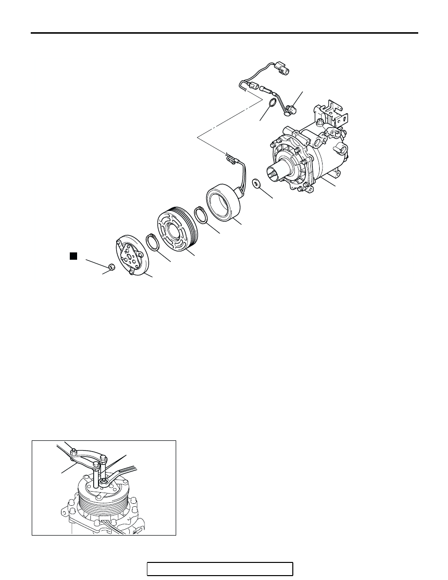
DISASSEMBLY AND ASSEMBLY

M1552004600659

Required Special Tools:

• MB991367: Special Spanner

• MB991386: Pin

DISASSEMBLY SERVICE POINT

.

<<A>> SELF-LOCKING NUT REMOVAL

AC209643AB

2

1

10

9

8

7

6

5

4

N

16 ± 1 N·m
12 ± 1 ft-lb

3

COOLING TEMPERATURE 
SWITCH DISASSEMBLY STEPS

1.

SNAP RING

2.

COOLING TEMPERATURE 
SWITCH
AIR CONDITIONING 
COMPRESSOR CLUTCH 
DISASSEMBLY

>>D<<

AIR GAP ADJUSTMENT

<<A>>>C<<

3.

SELF-LOCKING NUT

4.

ARMATURE

5.

SHIM

>>B<<

6.

SNAP RING

7.

ROTOR

8.

SNAP RING

>>A<<

9.

FIELD CORE

10. A/C COMPRESSOR

AIR CONDITIONING 
COMPRESSOR CLUTCH 
DISASSEMBLY (Continued)

AC209645AB

MB991386

MB991367

COMPRESSOR ASSEMBLY AND TENSION PULLEY

TSB Revision

HEATER, AIR CONDITIONING AND VENTILATION

55A-281

ASSEMBLY SERVICE POINTS

.

>>A<< FIELD CORE ATTACHMENT

Line up the pin hole on the compressor unit with the field core 
projection and attach.

.

>>B<< SNAP RING INSTALLATION

Using snap ring pliers, fit the snap ring so that the snap ring’s 
tapered part is on the outside.

.

>>C<< SELF-LOCKING NUT INSTALLATION

Using a special tool, as when removing the nut, secure the 
armature and tighten the self-locking nut.

.

>>D<< AIR GAP ADJUSTMENT

Check whether or not the air gap of the clutch is within the stan-
dard value.

Standard value:

 0.3 

 0.5 mm (0.012  0.020 inch)

NOTE: If there is a deviation of the air gap from the standard 
value, make the necessary adjustment by adjusting the number 
of shims.

AC209648AB

FIELD CORE 
PROJECTION

COMPRESSOR
UNIT PIN HOLE

AC001412

SNAP RING

ROTOR

CLUTCH COIL

TAPERED PART

AB

AC209650AB

THICKNESS
GAUGE

COMPRESSOR ASSEMBLY AND TENSION PULLEY

TSB Revision

HEATER, AIR CONDITIONING AND VENTILATION

55A-282

INSPECTION

M1552014301094

COOLING TEMPRATURE SWITCH

CAUTION

Do not heat more than necessary.
1. Dip the metal part of the cooling temperature switch into 

engine oil and increase the oil temperature using a gas 
burner or similar.

2. When the oil temperature reaches the standard value, check 

that voltage is supplied between the terminals.

Standard value: 

NOTE: When the oil temperature is 155

°

C (311

°

F) or more 

and there is no continuity, the resistance will not be 2

 or 

lower until the oil temperature reduces to 125

°

C (257

°

F) or 

less.

ITEM

TEMPERATURE

Less than 2 ohms

Slightly below 155

°C (311°F)

No continuity

155

°C (311°F) or more

AC100787

THERMOMETER

ENGINE OIL

AB

AC100810

LESS THAN 2

Ω 

NO CONTINUITY

125˚C 
(
257˚F)

155˚C 
(
311˚F)

OIL TEMPRATURE

AE

CONDENSER AND CONDENSER FAN MOTOR

TSB Revision

HEATER, AIR CONDITIONING AND VENTILATION

55A-283

CONDENSER AND CONDENSER FAN MOTOR

REMOVAL AND INSTALLATION

M1552006700414

Pre-removal and Post-installation Operation
• Refrigerant Draining and Refilling (Refer to 

P.55A-260

).

• Air Duct Removal and Installation (Refer to GROUP 15, 

Air Cleaner 

P.15-4

).

• Radiator Grilles Removal and Installation (Refer to 

GROUP 51, Radiator Grilles 

P.51-5

).

• Front End Structure Bar Removal and Installation (Refer 

to GROUP 14, Radiator 

P.14-11

).

AC306985

4.9 ± 0.9 N·m 
44 ± 8 in-ft

12 ± 2 N·m 
107 ± 17 in-ft

12 10

11

14

12

7

8

6

8

13

13

2

4

5

3

1

9

N

N

AB

<2.4 L engine>

CONDENSER FAN MOTOR 
REMOVAL STEPS

1.

CONDENSER FAN ASSEMBLY

2.

FAN

3.

COVER

4.

MOTOR

5.

SHROUD

RADIATOR GRILLES

FRONT END STRUCTURE BAR

CONDENSER REMOVAL STEPS

<<A>>

6.

FLEXIBLE DISCHARGE HOSE 
CONNECTION

<<A>>

7.

LIQUID PIPE A CONNECTION

8.

O-RING

FRONT UNDER COVER

9.

CONDENSER ASSEMBLY

10. RECEIVER

>>A<<

11. CONDENSER
12. UNDER BRACKET
13. UPPER BRACKET


Content   ..  299  300  301  302   ..