Mitsubishi Galant 9G. Manual - part 291


  Index      Mitsubishi     Mitsubishi Galant 9G - service repair manual


Search            


Content   ..  289  290  291  292   ..


Mitsubishi Galant 9G. Manual - part 291


MANUAL A/C DIAGNOSIS

TSB Revision

HEATER, AIR CONDITIONING AND VENTILATION

55A-240

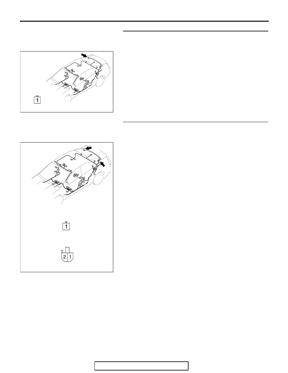
STEP 15. Check defogger connector D-08 for loose, 
corroded or damaged terminals, or terminals pushed back 
in the connector.
Q: Is defogger connector D-08 in good condition?

YES : Go to Step 16.
NO :  Repair or replace the connector. Refer to GROUP 

00E, Harness Connector Inspection 

P.00E-2

. Check 

that the defogger system works normally.

STEP 16. Check the wiring harness between defogger 
connector D-08 (terminal 1) and choke coil connector D-13 
(terminal 1).
Q: Is the wiring harness between defogger connector D-08 

(terminal 1) and choke coil connector D-13 (terminal 1) 
in good condition?
YES : 
Go to Step 17.
NO :  Repair or replace the wiring harness. Refer to 

GROUP 00E, Harness Connector Inspection 

P.00E-2

. Check that the defogger system works 

normally.

AC305268

CONNECTOR: D-08

AK

HARNESS SIDE

AC305269

CONNECTORS: D-08, D-13

D-08

D-13

HARNESS SIDE

D-08

HARNESS SIDE

D-13

AD

MANUAL A/C DIAGNOSIS

TSB Revision

HEATER, AIR CONDITIONING AND VENTILATION

55A-241

STEP 17. Check the defogger.
(1) Let the engine run at 2,000 r/min, and check the printed 

heater with the battery fully charged.

(2) Turn on the defogger switch, and use a voltmeter to 

measure the voltage in each printed heater at middle point 
A on the rear window glass.

• The value should be approximately 6 volts.

Q: Does the defogger work normally? 

YES : Replace the A/C-ECU. Check that the defogger 

system works normally.

NO :  Repair the defogger.

INSPECTION PROCEDURE 9:  Defogger Timer Function does not Operate.

.

CIRCUIT OPERATION

Turn ON the defogger switch. If the defogger does 
not shut off after about 16 minutes then the defogger 
timer is malfunctioning.

.

TROUBLESHOOTING HINT

• Malfunction of the A/C-ECU

• Malfunction of the defogger timer

DIAGNOSIS

Replace the A/C-ECU.

12 V

6V

0V

12 V

6V

0V

AC100595

A

NORMAL CHARACTERISTIC CURVE

ABNORMAL CHARACTERISTIC CURVE

VOLTAGE

A (CENTER POINT)

APPROXIMATELY
                         6 V

NEGATIVE
TERMINAL

PRINTED 
HEATER
LINE

POSITIVE
TERMINAL

NEGATIVE
TERMINAL

PRINTED 
HEATER
LINE

POSITIVE
TERMINAL

OPENCIRCUIT 
POINT

VOLTAGE

AB

MANUAL A/C DIAGNOSIS

TSB Revision

HEATER, AIR CONDITIONING AND VENTILATION

55A-242

INSPECTION PROCEDURE 10: Malfunction of the A/C-ECU Power Supply System.

IGNITION
SWITCH (IG2)

IGNITION
SWITCH (ACC)

BATTERY

RELAY
BOX

JOINT
CONNECTOR (1)

JOINT
CONNECTOR (2)

JUNCTION
BLOCK

JOINT
CONNECTOR (2)

POWER SUPPLY

A/C-ECU

A/C-ECU Power Supply Circuit

AC305231CI

CONNECTORS: C-01, C-03, C-29

C-01

C-03

C-29

AC305233

C-16 (B)

C-15 (B)

CONNECTORS: C-15, C-16

BE

MANUAL A/C DIAGNOSIS

TSB Revision

HEATER, AIR CONDITIONING AND VENTILATION

55A-243

.

TECHNICAL DESCRIPTION (COMMENT)

The A/C-ECU power system may be defective if the 
air conditioner, defogger, and outside/inside air 
selection damper motor all do not operate normally.

.

TROUBLESHOOTING HINTS

• Malfunction of the A/C-ECU

• Damaged harness wires or connectors

DIAGNOSIS

Required Special Tool:

• MB991223: Test Harness Set

STEP 1. Check A/C-ECU connector C-16 for loose, 
corroded or damaged terminals, or terminals pushed back 
in the connector.
Q:  Is A/C-ECU connector C-16 in good condition?

YES : Go to Step 2.
NO :  Repair or replace the connector. Refer to GROUP 

00E, Harness Connector Inspection 

P.00E-2

. Check 

that the air conditioning works normally.

AC305415

CONNECTORS: C-211, C-215

JUNCTION BLOCK 
(FRONT VIEW)

C-215

C-211

BA

AC305233

HARNESS SIDE

C-16 (B)

21

22

23

24

25

26

27

28

29

30

31

32

33

34

35

36

BX

CONNECTOR: C-16


Content   ..  289  290  291  292   ..