Mitsubishi Galant 9G. Manual - part 289


  Index      Mitsubishi     Mitsubishi Galant 9G - service repair manual


Search            


Content   ..  287  288  289  290   ..


Mitsubishi Galant 9G. Manual - part 289


MANUAL A/C DIAGNOSIS

TSB Revision

HEATER, AIR CONDITIONING AND VENTILATION

55A-232

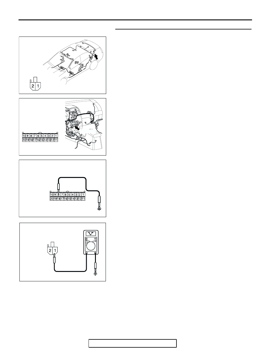
STEP 5. Measure the voltage at choke coil connector D-14. 
(1) Disconnect choke coil connector D-14, and measure the 

voltage at the harness side.

(2) Disconnect A/C-ECU connector C-15 and ground harness 

side terminal No.27.

(3) Turn the ignition switch to the "ON" position.

(4) Measure the voltage between choke coil connector D-14 

terminal No.1 and ground.

• The measured value should be approximately 12 volts 

(battery positive voltage).

Q: Is the measured voltage approx. 12 volts?

YES :  Go to Step 13.
NO :   Go to Step 6.

AC305268

CONNECTOR: D-14

AJ

HARNESS SIDE

AC305233

CONNECTOR: C-15

BG

C-105 (B)

HARNESS SIDE

AC306911

AC306911

CONNECTOR C-15 
(HARNESS SIDE)

AC

AC209365GZ

CONNECTOR D-14 
(HARNESS SIDE)

MANUAL A/C DIAGNOSIS

TSB Revision

HEATER, AIR CONDITIONING AND VENTILATION

55A-233

STEP 6. Measure the voltage at defogger relay connector 
C-201. 
(1) Disconnect defogger relay connector C-201, and measure 

the voltage at the junction block side.

(2) Measure the voltage between terminal 5 and ground.

• The measured value should be approximately 12 volts 

(battery positive voltage).

Q: Is the measured voltage approx. 12 volts?

YES :  Go to Step 8.
NO :   Go to Step 7.

AC305415BE

CONNECTOR: C-201

JUNCTION BLOCK SIDE

JUNCTION BLOCK 
(FRONT VIEW)

AC209365

CONNECTOR C-201 
(JUNCTION BLOCK SIDE)

HA

MANUAL A/C DIAGNOSIS

TSB Revision

HEATER, AIR CONDITIONING AND VENTILATION

55A-234

STEP 7. Check the wiring harness between defogger relay 
connector C-201 (terminal 5) and the fusible link (1).

NOTE: Also check intermediate connector C-29 and junction 
block connector C-216 for loose, corroded, or damaged termi-
nals, or terminals pushed back in the connector. If intermediate 
connector C-29 and junction block connector C-216 is dam-
aged, repair or replace the connector as described in GROUP 
00E, Harness Connector Inspection 

P.00E-2

.

Q: Is the wiring harness between defogger relay connector 

C-201(terminal 5) and the fusible link (1) in good 
condition?
YES : 
It can be assumed that this malfunction is intermittent. 

Refer to GROUP 00, How to Use 
Troubleshooting/Inspection Service Points 

− How to 

Cope with Intermittent Malfunctions 

P.00-14

.

NO :  Repair the wiring harness. Check that the defogger 

system works normally.

AC305231AI

CONNECTOR: C-29

AC305416

CONNECTORS: C-201, C-216

JUNCTION BLOCK 
(FRONT VIEW)

HARNESS SIDE

C-201

C-216 (B)

C-216

C-201

JUNCTION BLOCK SIDE

AP

MANUAL A/C DIAGNOSIS

TSB Revision

HEATER, AIR CONDITIONING AND VENTILATION

55A-235

STEP 8. Measure the voltage at defogger relay connector 
C-201. 
(1) Disconnect defogger relay connector C-201, and measure 

the voltage at the junction block side.

(2) Turn the ignition switch to the "ON" position.

(3) Measure the voltage between terminal 1 and ground.

• The measured value should be approximately 12 volts 

(battery positive voltage).

Q: Is the measured voltage approx. 12 volts?

YES :  Go to Step 10.
NO :   Go to Step 9.

STEP 9. Check the wiring harness between defogger relay 
connector C-201 (terminal 1) and ignition switch (IG2).

AC305415BE

CONNECTOR: C-201

JUNCTION BLOCK SIDE

JUNCTION BLOCK 
(FRONT VIEW)

AC209365HB

CONNECTOR C-201 
(JUNCTION BLOCK SIDE)

AC305416

CONNECTORS: C-201, C-215

JUNCTION BLOCK 
(FRONT VIEW)

HARNESS SIDE

C-201

JUNCTION BLOCK SIDE

C-201

C-215

C-215

AQ


Content   ..  287  288  289  290   ..