Mitsubishi Galant 9G. Manual - part 1611


  Index      Mitsubishi     Mitsubishi Galant 9G - service repair manual


Search            


Content   ..  1609  1610  1611  1612   ..


Mitsubishi Galant 9G. Manual - part 1611


ANTI-LOCK BRAKING SYSTEM (ABS) DIAGNOSIS

TSB Revision

ANTI-LOCK BRAKING SYSTEM (ABS)

35B-28

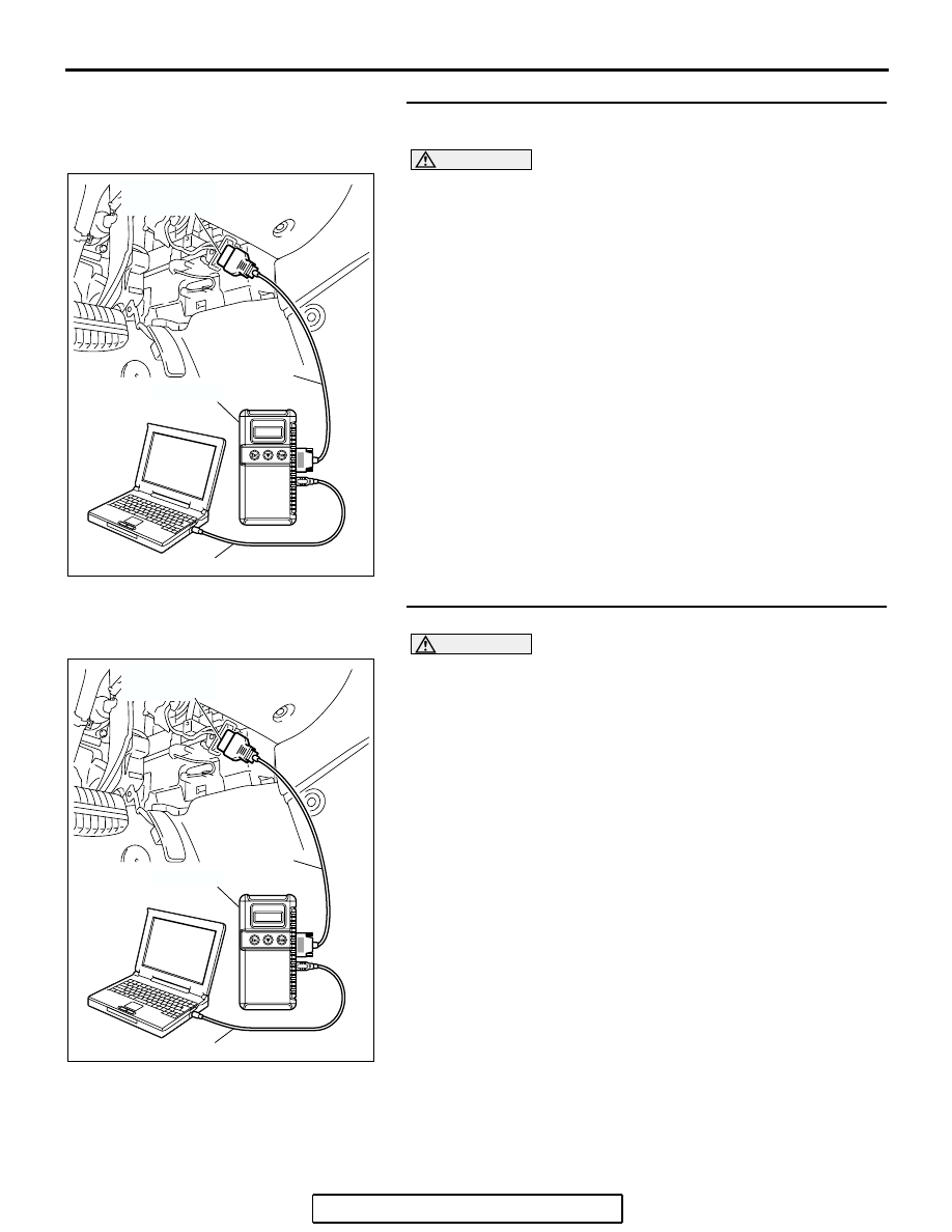
STEP 1. Using scan tool MB991958, diagnose the CAN bus 
line.

CAUTION

To prevent damage to scan tool MB991958, always turn the 
ignition switch to the "LOCK" (OFF) position before con-
necting or disconnecting scan tool MB991958.
(1) Connect scan tool MB991958 to the data link connector.
(2) Turn the ignition switch to the "ON" position.
(3) Diagnose the CAN bus line.
(4) Turn the ignition switch to the "LOCK" (OFF) position.
Q: Is the CAN bus line found to be normal?

YES : Go to Step 3
NO :  Repair the CAN bus line (Refer to GROUP 54C, 

Diagnosis 

P.54C-14

).  Then go to Step 2.

STEP 2. Recheck for diagnostic trouble code.

CAUTION

To prevent damage to scan tool MB991958, always turn the 
ignition switch to the "LOCK" (OFF) position before con-
necting or disconnecting scan tool MB991958.
(1) Turn the ignition switch to the "ON" position.
(2) Erase the DTC.
(3) Turn the ignition switch to the "LOCK" (OFF) position.
(4) Turn the ignition switch to the "ON" position.
(5) Check if the DTC is set.
(6) Turn the ignition switch to the "LOCK" (OFF) position.
Q: Is DTC C1201, C1206, C1211 or C1216 set?

YES : Go to Step 3
NO :  The procedure is complete.

AC305412

AB

MB991910

DATA LINK

CONNECTOR

MB991824

MB991827

AC305412

AB

MB991910

DATA LINK

CONNECTOR

MB991824

MB991827

ANTI-LOCK BRAKING SYSTEM (ABS) DIAGNOSIS

TSB Revision

ANTI-LOCK BRAKING SYSTEM (ABS)

35B-29

STEP 3. Using scan tool MB991958, read the diagnostic 
trouble code.

CAUTION

To prevent damage to scan tool MB991958, always turn the 
ignition switch to the "LOCK" (OFF) position before con-
necting or disconnecting scan tool MB991958.
Use scan tool MB991958 to check whether DTC codes C1200, 
C1205, C1210 and C1215 have been set simultaneously.
(1) Connect scan tool MB991958 to the data link connector.
(2) Turn the ignition switch to the "ON" position.
(3) Check whether DTC C1200, C1205, C1210 or C1215 have 

been set.

(4) Turn the ignition switch to the "LOCK" (OFF) position.
Q: Is DTC C1200, C1205, C1210 or C1215 set?

YES : Carry out diagnosis relevant to DTC C1200, C1205, 

C1210 or C1215 (Refer to 

P.35B-10

).

NO :  Go to Step 4.

STEP 4. Check the installation condition of the wheel 
speed sensors.
For the wheel speed sensor, which the DTC code indicates, 
check whether the sensor or its mounting bolts are loosened.

• DTC C1201 is set: Front right wheel speed sensor

• DTC C1206 is set: Front left wheel speed sensor

• DTC C1211 is set: Rear right wheel speed sensor

• DTC C1216 is set: Rear left wheel speed sensor

Q: Is the wheel speed sensor installed correctly?

YES : Go to Step 5.
NO :  Reinstall the wheel speed sensor correctly. Then go 

to Step 16.

STEP 5. Check the wheel speed sensor after it is removed 
from the vehicle.
Check the wheel speed sensor which the DTC code indicates 
(Refer to 

P.35B-108

).

• DTC C1201 is set: Front right wheel speed sensor

• DTC C1206 is set: Front left wheel speed sensor

• DTC C1211 is set: Rear right wheel speed sensor

• DTC C1216 is set: Rear left wheel speed sensor

Q: Is the wheel speed sensor in good condition?

YES : Go to Step 6.
NO :  Replace the wheel speed sensor (Refer to 

P.35B-107

). Then go to Step 16.

AC305412

AB

MB991910

DATA LINK

CONNECTOR

MB991824

MB991827

ANTI-LOCK BRAKING SYSTEM (ABS) DIAGNOSIS

TSB Revision

ANTI-LOCK BRAKING SYSTEM (ABS)

35B-30

STEP 6. Check the wheel bearing for looseness.
NOTE: If the wheel bearing is loose, the gap between the 
wheel speed sensor and rotor may become excessive. Check 
the wheel bearing, which DTC code indicates, for looseness.

• DTC C1201 is set: Check the front right wheel bearing 

(Refer to GROUP 26, On-vehicle service 

− Wheel bearing 

end play check 

P.26-8

).

• DTC C1206 is set: Check the front left wheel bearing (Refer 

to GROUP 26, On-vehicle service 

− Wheel bearing end play 

check 

P.26-8

).

• DTC C1211 is set: Check the rear right wheel bearing 

(Refer to GROUP 27, On-vehicle service 

− Wheel bearing 

end play check 

P.27-4

).

• DTC C1216 is set: Check the rear left wheel bearing (Refer 

to GROUP 27, On-vehicle service 

− Wheel bearing end play 

check 

P.27-4

)

Q: Is the wheel bearing end play within the standard value?

YES : Go to Step 7.
NO (front bearing end play is not within the standard 
value) : 
Replace the front hub assembly (Refer to GROUP 

26, Front axle hub assembly 

P.26-9

).

NO (rear bearing end play is not within the standard 
value) : 
Replace the rear hub assembly (Refer to GROUP 

27, Rear axle hub assembly 

P.27-4

).

STEP 7. Check the wheel speed rotor.
Check the wheel speed rotor, which DTC code indicates, for 
foreign material or deformation.

• DTC C1201 is set: Front right wheel speed sensor

• DTC C1206 is set: Front left wheel speed sensor

• DTC C1211 is set: Rear right wheel speed sensor

• DTC C1216 is set: Rear left wheel speed sensor

Q: Is the wheel speed rotor in good condition?

YES : Go to Step 8.
NO (front bearing end play is not within the standard 
value) : 
If the wheel speed rotor is contaminated with 

foreign material, clean it.  If the driveshaft is 
deformed, replace it (Refer to GROUP 26, Drive shaft 
assembly 

P.26-13

).

NO (rear bearing end play is not within the standard 
value) : 
If the wheel speed rotor is contaminated with 

foreign material, clean it.  If the wheel speed rotor is 
deformed, replace it (Refer to GROUP 27, Rear axle 
hub assembly 

P.27-6

).

ANTI-LOCK BRAKING SYSTEM (ABS) DIAGNOSIS

TSB Revision

ANTI-LOCK BRAKING SYSTEM (ABS)

35B-31

STEP 8. Measure the voltage at ABS-ECU connector A-02.
(1) Disconnect the connector A-02, and connect special tool 

ABS Check Harness (MB991970) to the wiring 
harness-side connector.
NOTE: Do not connect special tool ABS Check Harness 
(MB991970) to the ABS-ECU.

(2) Turn the ignition switch to the "ON" position.
(3) Measure the voltage between the relevant signal and 

ground terminals in the wheel speed sensor circuit and 
body ground. It should be less than 1V.

• DTC C1201 is set: Between signal terminal 9 and body 

ground, and between ground terminal 10 and body 
ground

• DTC C1206 is set: Between signal terminal 26 and body 

ground, and between ground terminal 16 and body 
ground

• DTC C1211 is set: Between signal terminal 11 and body 

ground, and between ground terminal 17 and body 
ground

• DTC C1216 is set: Between signal terminal 28 and body 

ground, and between ground terminal 27 and body 
ground

Q: Does the voltage measure 1 V or less?

YES : Go to Step 9.
NO (When the voltage between terminal 9 or 10 

 and 

body ground measures more than 1 V) : Go to Step 11.
NO (When the voltage between terminal 26 or 16 

 and 

body ground measures more than 1 V) : Go to Step 12.
NO (When the voltage between terminal 11 or 17 

 and 

body ground measures more than 1 V) : Go to Step 13.
NO (When the voltage between terminal 28 or 27 

 and 

body ground measures more than 1 V) : Go to Step 14.

AC306403

19

2

18

1

8

9

7

6

5

4

3

10

11   

25

15

16

17

27

28

26

12

13

14

23

24

22 21 20

AB

ABS-ECU

MB991970

CHECK CONNECTOR

A-02 HARNESS
CONNECTOR

A-02 (GR)

CONNECTOR: A-02

HYDRAULIC UNIT
(WITH BUILT-IN ABS-ECU)


Content   ..  1609  1610  1611  1612   ..