Mitsubishi Galant 9G. Manual - part 1610


  Index      Mitsubishi     Mitsubishi Galant 9G - service repair manual


Search            


Content   ..  1608  1609  1610  1611   ..


Mitsubishi Galant 9G. Manual - part 1610


ANTI-LOCK BRAKING SYSTEM (ABS) DIAGNOSIS

TSB Revision

ANTI-LOCK BRAKING SYSTEM (ABS)

35B-24

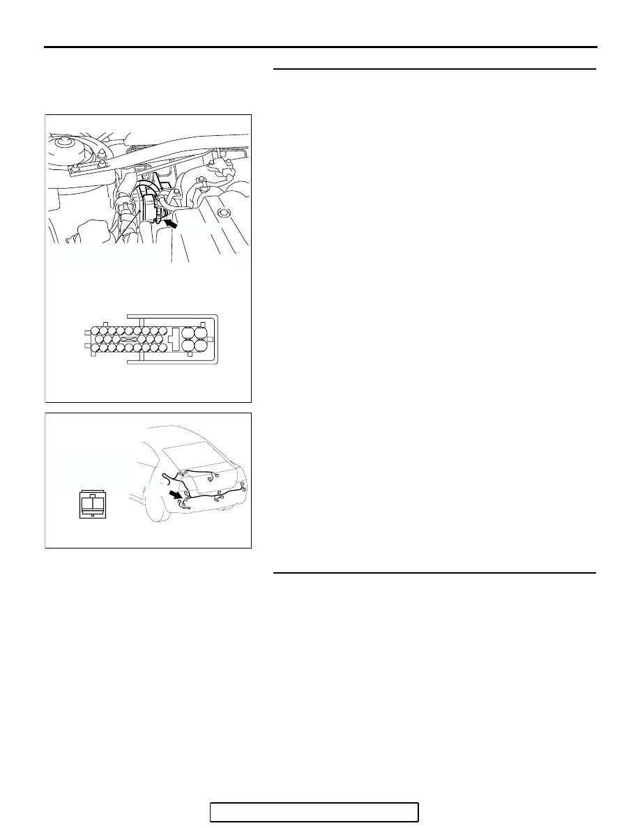
STEP 14. Check the harness wires between ABS-ECU 
connector A-02 (terminal 28, 27) and wheel speed sensor 
<rear: LH> connector F-07 (terminal 1, 2).
Q: Is the harness wire between ABS-ECU connector A-02 ( 

terminal 28, 27) and wheel speed sensor <rear: LH> 
connector F-07 (terminal 1, 2) damaged?
YES : 
Repair the wiring harness. Then go to Step 17.
NO :  Go to Step 15.

STEP 15. Inspect the wheel speed sensor.
Check the wheel speed sensor relevant to the DTC code. For 
the applicable inspection procedure, refer to 

P.35B-108

.

• When DTC code C1200 is set: Front right wheel speed sen-

sor

• When DTC code C1205 is set: Front left wheel speed sen-

sor

• When DTC code C1210 is set: Rear right wheel speed sen-

sor

• When DTC code C1215 is set: Rear left wheel speed sen-

sor

Q: Is the wheel speed sensor damaged?

YES :  Replace the wheel speed sensor. Then go to Step 

17.

NO :  Go to Step 4.

AC306406

19

2

18

1

8

9

7

6

5

4

3

10

11   

25

15

16

17

27

28

26

12

13

14

23

24

22 21 20

A-02 HARNESS CONNECTOR
(HARNESS SIDE)

AB

A-02 (GR)

CONNECTOR: A-02

HYDRAULIC UNIT
(WITH BUILT-IN ABS-ECU)

AC305260

CONNECTOR: F-07

AG

F-07 HARNESS
CONNECTOR
(HARNESS SIDE)

1 2

F-07

ANTI-LOCK BRAKING SYSTEM (ABS) DIAGNOSIS

TSB Revision

ANTI-LOCK BRAKING SYSTEM (ABS)

35B-25

STEP 16. Recheck for diagnostic trouble code.
Check again if the DTC is set.
(1) Turn the ignition switch to the "ON" position.
(2) Erase the DTC.
(3) Turn the ignition switch to the "LOCK" (OFF) position.
(4) Turn the ignition switch to the "ON" position.
(5) Check if the DTC is reset.
(6) Turn the ignition switch to the "LOCK" (OFF) position.
Q: Is DTC C1200, C1205, C1210 or C1215 set?

YES : Replace the hydraulic unit (integrated with 

ABS-ECU). Then go to Step 17.

NO :  It can be assumed that this malfunction is intermittent. 

Refer to GROUP 00, How to Use 
Troubleshooting/Inspection Service Points 

− How to 

Cope with Intermittent Malfunction 

P.00-14

.

STEP 17. Recheck for diagnostic trouble code.
(1) Turn the ignition switch to the "ON" position.
(2) Erase the DTC.
(3) Turn the ignition switch to the "LOCK" (OFF) position.
(4) Turn the ignition switch to the "ON" position.
(5) Check if the DTC is set.
(6) Turn the ignition switch to the "LOCK" (OFF) position.
Q: Is DTC C1200, C1205, C1210 or C1215 set?

YES : Repeat the troubleshooting from Step 1.
NO :  The procedure is complete.

AC305412

AB

MB991910

DATA LINK

CONNECTOR

MB991824

MB991827

AC305412

AB

MB991910

DATA LINK

CONNECTOR

MB991824

MB991827

ANTI-LOCK BRAKING SYSTEM (ABS) DIAGNOSIS

TSB Revision

ANTI-LOCK BRAKING SYSTEM (ABS)

35B-26

DTC C1201/C1206/C1211/1216 Wheel Speed Sensor (Abnormal Output Signal)

WHEEL SPEED SENSOR

WHEEL SPEED SENSOR

(REAR: RH)

(REAR: LH)

(FRONT: RH)

(FRONT: LH)

ABS-ECU

Wheel Speed Sensor Circuit

AC305206

A-01 (B)

CONNECTOR: A-01

AT

AC304742

A-02 (GR)

CONNECTOR: A-02

HYDRAULIC UNIT
(WITH BUILT-IN ABS-ECU)

AC

AC305210AI

A-04(B)

CONNECTOR: A-04

AC305231BL

CONNECTOR: C-25

C-25

ANTI-LOCK BRAKING SYSTEM (ABS) DIAGNOSIS

TSB Revision

ANTI-LOCK BRAKING SYSTEM (ABS)

35B-27

CAUTION

If there is any problem in the CAN bus lines, an 
incorrect diagnostic trouble code may be set. 
Prior to this diagnosis, diagnose the CAN bus 
lines.

.

CIRCUIT OPERATION

• A toothed wheel speed rotor generates a voltage 

pulse as it moves across the pickup field of each 
wheel speed sensor.

• The amount of voltage generated at each wheel 

is determined by the clearance between the 
wheel speed rotor teeth and the wheel speed 
sensor, and by the speed of rotation.

• Sends alternating current signals at frequencies 

which are proportional to the rotation speeds of 
each wheel to the ABS electronic control unit 
(ABS-ECU).

• The ABS hydraulic unit modulates the amount of 

braking force individually applied to each wheel 
cylinder.

.

ABS DTC  SET CONDITIONS

The ABS-ECU monitors the signals from each wheel 
speed sensor while the vehicle is being driven. If any 
fault below is found in these sensor signals, the ECU 
will set the relevant diagnostic trouble code.

• Missing sensor signal

• Sensor signal, which will not be created under 

normal operation

• Significant difference among the wheel speed 

sensor signals

.

TROUBLESHOOTING HINTS (The most 
likely causes for these DTCs are to set 
are:)

Current trouble

• Malfunction of the wheel speed sensor or wheel 

speed rotor

• Damaged wiring harness or connector

• Malfunction of the hydraulic unit (integrated with 

ABS-ECU)

Past  trouble

• Carry out diagnosis with particular emphasis on 

connector(s) or wiring harness in wheel speed 
sensor circuit. For diagnosis procedures, refer to 
"How to cope with past trouble" (Refer to GROUP 
00, How to use Troubleshooting/Inspection Ser-
vice Points

P.00-16

).

.

Past trouble

For diagnosis procedures, refer to "How to cope with 
past trouble" (Refer to GROUP 00, How to Use Trou-
bleshooting 

P.00-16

).

.

DIAGNOSIS

Required Special Tools:

• MB991958: Scan Tool (MUT-III Sub Assembly)

• MB991824: Vehicle Communication Interface (V.C.I.)

• MB991827: MUT-III USB Cable

• MB991910: MUT-III Main Harness A

• MB991970: ABS Check Harness

.

AC305260

F-04

F-07

CONNECTORS: F-04, F-07

AB


Content   ..  1608  1609  1610  1611   ..