Mitsubishi Galant 9G. Manual - part 1607


  Index      Mitsubishi     Mitsubishi Galant 9G - service repair manual


Search            


Content   ..  1605  1606  1607  1608   ..


Mitsubishi Galant 9G. Manual - part 1607


ANTI-LOCK BRAKING SYSTEM (ABS) DIAGNOSIS

TSB Revision

ANTI-LOCK BRAKING SYSTEM (ABS)

35B-12

TROUBLESHOOTING HINTS (The most 
likely causes for these DTCs are to set 
are:)

Current trouble

• Malfunction of the wheel speed sensor

• Damaged wiring harness or connector

• Malfunction of the hydraulic unit (integrated with 

ABS-ECU)

Past  trouble

• Carry out diagnosis with particular emphasis on 

connector(s) or wiring harness in wheel speed 
sensor circuit. For diagnosis procedures, refer to 
"How to cope with past trouble" (Refer to GROUP 
00, How to use Troubleshooting/Inspection Ser-
vice Points

P.00-16

).

.

DIAGNOSIS

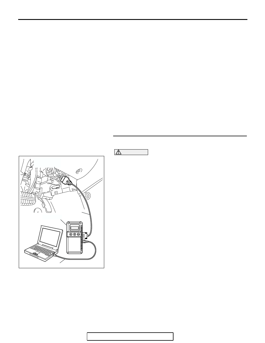
Required Special Tools:

• MB991958: Scan Tool (MUT-III Sub Assembly)

• MB991824: Vehicle Communication Interface (V.C.I.)

• MB991827: MUT-III USB Cable

• MB991910: MUT-III Main Harness A

• MB991970: ABS Check Harness

.

STEP 1. Using scan tool MB991958, diagnose the CAN bus 
line.

CAUTION

To prevent damage to scan tool MB991958, always turn the 
ignition switch to the "LOCK" (OFF) position before con-
necting or disconnecting scan tool MB991958.
(1) Connect scan tool MB991958 to the data link connector.
(2) Turn the ignition switch to the "ON" position.
(3) Diagnose the CAN bus line.
(4) Turn the ignition switch to the "LOCK" (OFF) position.
Q: Is the CAN bus line found to be normal?

YES : Go to Step 3
NO :  Repair the CAN bus line (Refer to GROUP 54C, 

Diagnosis 

P.54C-14

). Then go to Step 2.

AC305412

AB

MB991910

DATA LINK

CONNECTOR

MB991824

MB991827

ANTI-LOCK BRAKING SYSTEM (ABS) DIAGNOSIS

TSB Revision

ANTI-LOCK BRAKING SYSTEM (ABS)

35B-13

STEP 2. Recheck for diagnostic trouble code.

CAUTION

To prevent damage to scan tool MB991958, always turn the 
ignition switch to the "LOCK" (OFF) position before con-
necting or disconnecting scan tool MB991958.
(1) Turn the ignition switch to the "ON" position.
(2) Erase the DTC.
(3) Turn the ignition switch to the "LOCK" (OFF) position.
(4) Turn the ignition switch to the "ON" position.
(5) Check if the DTC is set.
(6) Turn the ignition switch to the "LOCK" (OFF) position.
Q: Is DTC C1200, C1205, C1210 or C1215 set?

YES : Go to Step 3
NO :  The procedure is complete.

STEP 3. Using scan tool MB991958, check data list.

CAUTION

To prevent damage to scan tool MB991958, always turn the 
ignition switch to the "LOCK" (OFF) position before con-
necting or disconnecting scan tool MB991958.
(1) Connect scan tool MB991958 to the data link connector.
(2) Start the engine.
(3) Set scan tool MB991958 to the data reading mode, and 

check the data list items by driving the vehicle.

• Item 01 (DTC C1200 is set): Front right wheel speed 

sensor

• Item 02 (DTC C1205 is set): Front left wheel speed sen-

sor

• Item 03 (DTC C1210 is set): Rear right wheel speed 

sensor

• Item 04 (DTC C1215 is set): Rear left wheel speed sen-

sor

(4) Turn the ignition switch to the "LOCK" (OFF) position.
Q: Does the speedometer indication match the scan tool 

indication?
YES : 
It can be assumed that this malfunction is intermittent. 

Refer to GROUP 00, How to Use 
Troubleshooting/Inspection Service Points 

− How to 

Cope with Intermittent Malfunction 

P.00-14

.

NO :  Go to Step 4.

AC305412

AB

MB991910

DATA LINK

CONNECTOR

MB991824

MB991827

AC305412

AB

MB991910

DATA LINK

CONNECTOR

MB991824

MB991827

ANTI-LOCK BRAKING SYSTEM (ABS) DIAGNOSIS

TSB Revision

ANTI-LOCK BRAKING SYSTEM (ABS)

35B-14

STEP 4. Measure the voltage at ABS-ECU connector A-02.
(1) Disconnect the connector A-02, and connect special tool 

ABS Check Harness (MB991970) to the wiring 
harness-side connector.
NOTE: Do not connect special tool ABS Check Harness 
(MB991970) to the ABS-ECU.

(2) Turn the ignition switch to the "ON" position.
(3) Measure the voltage between the relevant signal and 

ground terminals in the wheel speed sensor circuit and 
body ground. It should be less than 1V.

• DTC C1201 is set: Between signal terminal 9 and body 

ground, and between ground terminal 10 and body 
ground

• DTC C1206 is set: Between signal terminal 26 and body 

ground, and between ground terminal 16 and body 
ground

• DTC C1211 is set: Between signal terminal 11 and body 

ground, and between ground terminal 17 and body 
ground

• DTC C1216 is set: Between signal terminal 28 and body 

ground, and between ground terminal 27 and body 
ground

Q: Does the voltage measure 1 V or less?

YES : Go to Step 5.
NO (When the voltage between terminal 9 or 10 

 and 

body ground measures more than 1 V) : Go to Step 7.
NO (When the voltage between terminal 26 or 16 

 and 

body ground measures more than 1 V) : Go to Step 9.
NO (When the voltage between terminal 11 or 17 

 and 

body ground measures more than 1 V) : Go to Step 11.
NO (When the voltage between terminal 28 or 27 

 and 

body ground measures more than 1 V) : Go to Step 13.

AC306403

19

2

18

1

8

9

7

6

5

4

3

10

11   

25

15

16

17

27

28

26

12

13

14

23

24

22 21 20

AB

ABS-ECU

MB991970

CHECK CONNECTOR

A-02 HARNESS
CONNECTOR

A-02 (GR)

CONNECTOR: A-02

HYDRAULIC UNIT
(WITH BUILT-IN ABS-ECU)

ANTI-LOCK BRAKING SYSTEM (ABS) DIAGNOSIS

TSB Revision

ANTI-LOCK BRAKING SYSTEM (ABS)

35B-15

STEP 5. Measure the resistance at ABS-ECU connector 
A-02.
(1) Disconnect the connector A-02, and connect special tool 

ABS Check Harness (MB991970) to the wiring 
harness-side connector.
NOTE: Do not connect special tool ABS Check Harness 
(MB991970) to the ABS-ECU.

(2) Measure the resistance between the relevant signal and 

ground terminals in the wheel speed sensor circuit and 
body ground. There should be no continuity.

• DTC C1201 is set: Between signal terminal 9 and body 

ground, and between ground terminal 10 and body 
ground

• DTC C1206 is set: Between signal terminal 26 and body 

ground, and between ground terminal 16 and body 
ground

• DTC C1211 is set: Between signal terminal 11 and body 

ground, and between ground terminal 17 and body 
ground

• DTC C1216 is set: Between signal terminal 28 and body 

ground, and between ground terminal 27 and body 
ground

Q: Does continuity exist?

YES (Continuity exists between terminal 9 or terminal 10 
and body ground) : 
Go to Step 7.
YES (Continuity exists between terminal 26 or terminal 
16 and body ground) : 
Go to Step 9.
YES (Continuity exists between terminal 11 or terminal 
17 and body ground) : 
Go to Step 11.
YES (Continuity exists between terminal 28 or terminal 
27 and body ground) : 
Go to Step 13.
NO :  Go to Step 6.

AC306403

19

2

18

1

8

9

7

6

5

4

3

10

11   

25

15

16

17

27

28

26

12

13

14

23

24

22 21 20

AC

ABS-ECU

MB991970

CHECK CONNECTOR

A-02 HARNESS
CONNECTOR

A-02 (GR)

CONNECTOR: A-02

HYDRAULIC UNIT
(WITH BUILT-IN ABS-ECU)


Content   ..  1605  1606  1607  1608   ..