Content .. 1597 1598 1599 1600 ..
Mitsubishi Galant 9G. Manual - part 1599
MULTI-CENTER DISPLAY
TSB Revision
CHASSIS ELECTRICAL
54A-268
.
CIRCUIT OPERATION
The A/C-ECU receives information on ambient air
temperature from the ambient air temperature sen-
sor. Then the information is sent to the multi-center
display unit (middle grade type) via CAN communi-
cation.
.
TECHNICAL DESCRIPTION (COMMENT)
If the A/C-ECU has not informed an ambient air tem-
perature via the CAN communication for 60 seconds
or more, "COM ERROR" appears on the screen. If
the multi-center display unit (middle grade type) can
not receive correct information from the ambient air
temperature sensor at all, "
−−°C (−−°F)" will be
shown.
.
TROUBLESHOOTING HINTS
• Malfunction of multi-center display unit (middle
grade type)
• Malfunction of A/C-ECU
• Malfunction of Ambient air temperature sensor.
• The wiring harness or connectors may have
loose, corroded, or damaged terminals, or termi-
nals pushed back in the connector.
AC305206
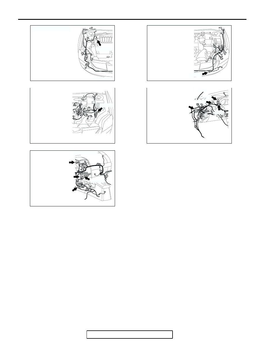
CONNECTOR: A-02
AO
A-02 (GR)
AC305210
A-25 (BR)
AQ
CONNECTOR: A-25
AC305216
B-19 (B)
CONNECTOR: B-19
AD
AC305231DE
CONNECTORS: C-02, C-03, C-29, C-101
C-02
C-03
C-29
C-101
AC305233
C-16 (B)
C-23
CONNECTORS: C-05,C-15, C-16,C-23
C-15 (B)
CR
C-05 (B)