Content .. 1596 1597 1598 1599 ..
Mitsubishi Galant 9G. Manual - part 1598
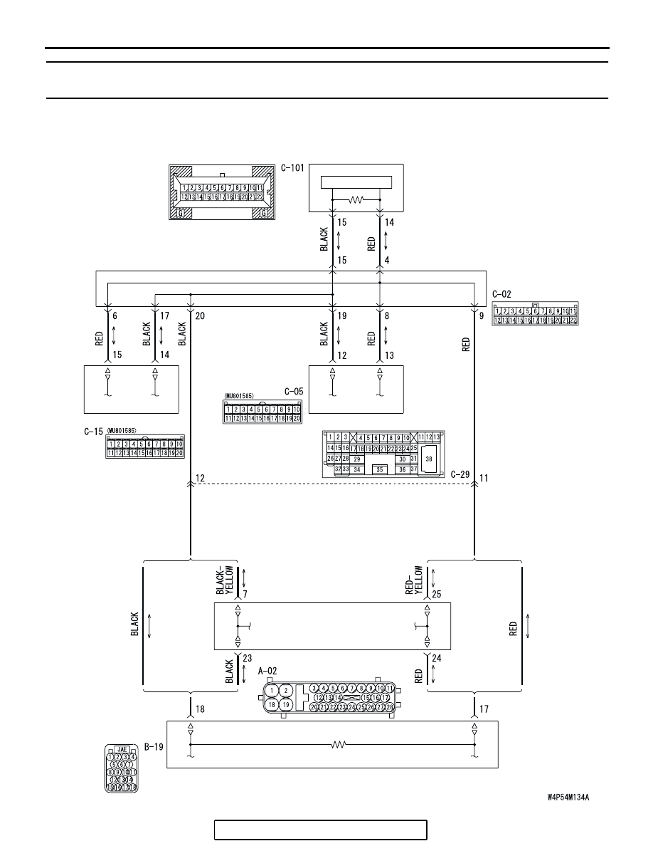
MULTI-CENTER DISPLAY
TSB Revision
CHASSIS ELECTRICAL
54A-264
INSPECTION PROCEDURE 3: The A/C Display Shows "COMMUNICATION ERROR", and then can not
Proceed to Next Screen. (Middle Grade Type)
POWERTRAIN
CONTROL MODULE
JOINT
CONNECTOR (3)
WITHOUT ELECTRONIC
BRAKE-FORCE
DISTRIBUTION (EBD)
AND ANTI-LOCK
BRAKING
SYSTEM (ABS)
WITH ELECTRONIC
BRAKE-FORCE
DISTRIBUTION (EBD)
AND ANTI-LOCK
BRAKING
SYSTEM (ABS)
WITH ELECTRONIC
BRAKE-FORCE
DISTRIBUTION (EBD)
AND ANTI-LOCK
BRAKING
SYSTEM (ABS)
WITHOUT ELECTRONIC
BRAKE-FORCE
DISTRIBUTION (EBD)
AND ANTI-LOCK
BRAKING
SYSTEM (ABS)
MULTI-CENTER
DISPLAY UNIT
CPU
A/C-ECU
COMBINATION METER
ABS-ECU OR ABS/TCL-ECU
CAN-BUS Line Circuit