Content .. 1588 1589 1590 1591 ..
Mitsubishi Galant 9G. Manual - part 1590
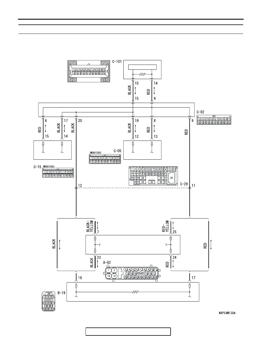
MULTI-CENTER DISPLAY
TSB Revision
CHASSIS ELECTRICAL
54A-232
DTC 013: A/C-ECU Time-out
POWERTRAIN
CONTROL MODULE
JOINT
CONNECTOR (3)
WITHOUT ELECTRONIC
BRAKE-FORCE
DISTRIBUTION (EBD)
AND ANTI-LOCK
BRAKING
SYSTEM (ABS)
WITH ELECTRONIC
BRAKE-FORCE
DISTRIBUTION (EBD)
AND ANTI-LOCK
BRAKING
SYSTEM (ABS)
WITH ELECTRONIC
BRAKE-FORCE
DISTRIBUTION (EBD)
AND ANTI-LOCK
BRAKING
SYSTEM (ABS)
WITHOUT ELECTRONIC
BRAKE-FORCE
DISTRIBUTION (EBD)
AND ANTI-LOCK
BRAKING
SYSTEM (ABS)
ABS-ECU OR ABS/TCL-ECU
MULTI-CENTER
DISPLAY UNIT
COMBINATION
METER
CPU
A/C-ECU
Circuit of Time-out During CAN Communication with A/C-ECU