Content .. 1556 1557 1558 1559 ..
Mitsubishi Galant 9G. Manual - part 1558
COMBINATION METER ASSEMBLY
TSB Revision
CHASSIS ELECTRICAL
54A-104
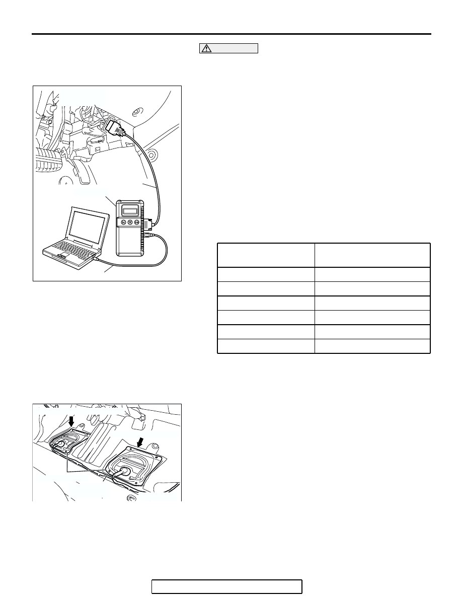
CAUTION
To prevent damage to scan tool MB991958, always turn the
ignition switch to the "LOCK" (OFF) position before con-
necting or disconnecting scan tool MB991958.
1. Connect scan tool MB991958 to the data link connector.
2. A/T select lever: "P" position.
3. Turn the ignition switch to "ON" position.
4. Start the engine.
5. Run the engine.
6. Select MFI system data list and take a reading of the engine
speed.
Item 22: CKP SENSOR
7. Compare the engine speed shown in the scan tool with that
shown on the tachometer. The engine speeds shown on the
tachometer should correspond to the table below.
NOTE: The following standard value assumes that battery
voltage is 13.5 volts.
Standard value :
FUEL LEVEL SENSOR CHECK
M1543001300037
1. Remove the rear seat cusion assembly. (Refer to GROUP
52A, Rear Seat Assembly
2. Remove hole cover and remove the fuel pump module and
fuel level sensor (sub).
Tightening torque: 1.5
± 0.5 N⋅m (14 ± 0.5 in-Ib)
Engine speed (r/min)
Indication allowance of
tachometer r/min
600
600
± 100
2,000
2,000
± 100
3,000
3,000
± 150
4,000
4,000
± 150
5,000
5,000
± 150
6,000
6,000
± 150
AC305412
AB
MB991910
DATA LINK
CONNECTOR
MB991824
MB991827
AC307098AB
FUEL PUMP MODULE
WIRING COVER
1.5 ± 0.5 N·m
14 ± 4 in-lb
FUEL LEVEL SENSOR (SUB)