Content .. 1506 1507 1508 1509 ..
Mitsubishi Galant 9G. Manual - part 1508
LOWER ARM
TSB Revision
REAR SUSPENSION
34-10
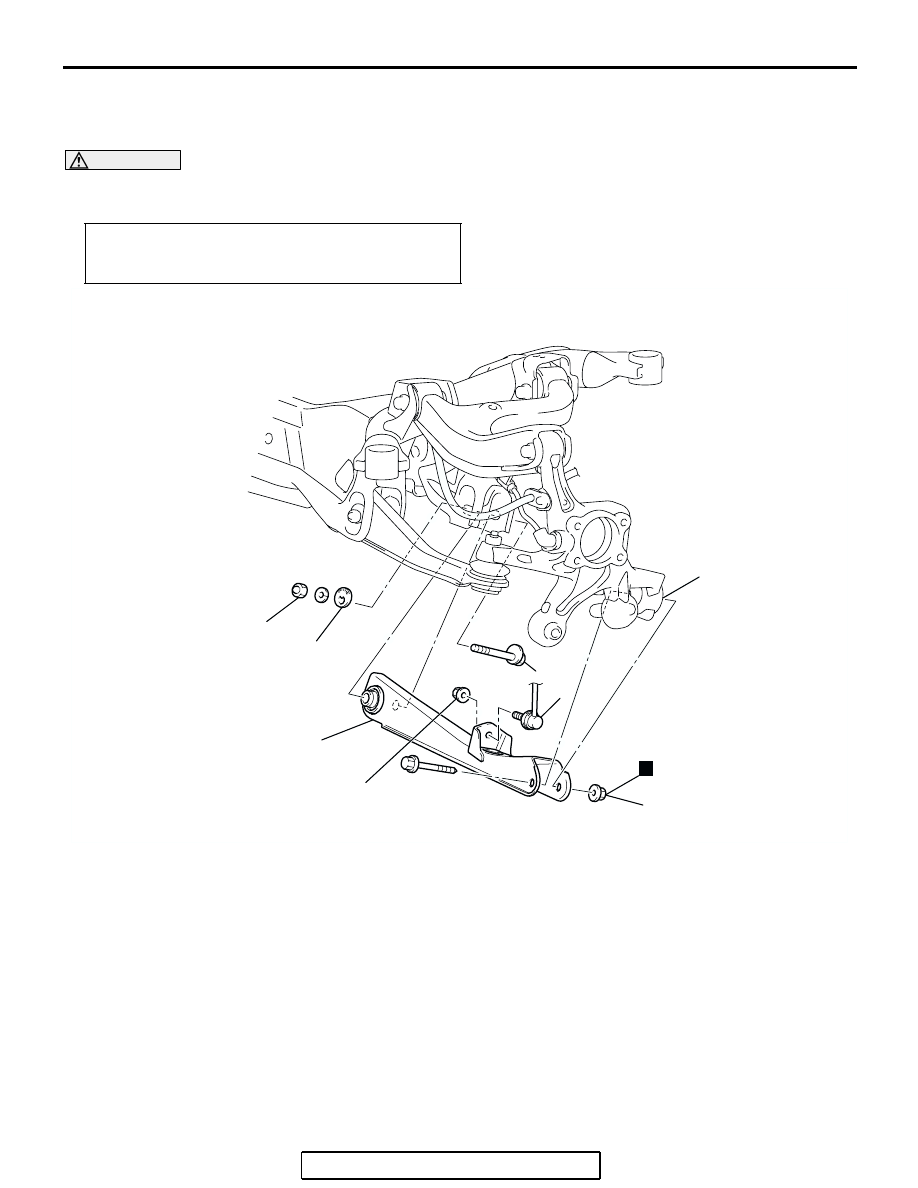
LOWER ARM
REMOVAL AND INSTALLATION
M1341006500047
CAUTION
*
: Indicates parts which should be temporarily tightened, and then fully tightened with the vehicle on
the ground in an unladen condition.
Post-installation Operation
• Rear Wheel Alignment Check and Adjustment (Refer to
AC305777
1
2
5
AB
78 ± 7 N·m*
57 ± 5 ft-lb*
N
113 ± 12 N·m*
83 ± 9 ft-lb*
40 ± 5 N·m
30 ± 3 ft-lb
3
4
REMOVAL STEPS
•
SHOCK ABSORBER ASSEMBLY
AND KNUCKLE CONNECTION
(REFER TO
1.
LOWER ARM ASSEMBLY AND
STABILIZER BAR LINK ASSEMBLY
CONNECTION
2.
LOWER ARM ASSEMBLY AND
KNUCKLE CONNECTION
<<A>>
3.
LOWER ARM BOLT
4.
LOWER ARM PLATE
5.
LOWER ARM ASSEMBLY
REMOVAL STEPS (Continued)