Mitsubishi Galant 9G. Manual - part 1438


  Index      Mitsubishi     Mitsubishi Galant 9G - service repair manual


Search            


Content   ..  1436  1437  1438  1439   ..


Mitsubishi Galant 9G. Manual - part 1438


SRS AIR BAG DIAGNOSIS

TSB Revision

SUPPLEMENTAL RESTRAINT SYSTEM (SRS)

52B-162

STEP 2. Recheck for diagnostic trouble code.
Check again if the DTC is set.
(1) Erase the DTC.
(2) Turn the ignition switch to "ON" position.
(3) Check if the DTC is set.
(4) Turn the ignition switch to the "LOCK" (OFF) position.

Q: Is the DTC set?

YES : Go to Step 3.
NO :  There is an intermittent malfunction such as poor 

engaged connector(s) or open circuit (Refer to 
GROUP 00, How to Use Troubleshooting/Inspection 
Service Points 

− How to Cope with Intermittent 

Malfunctions ).

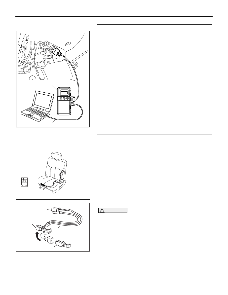
STEP 3. Check the side-airbag module (LH). (Using scan 
tool MB991958, read the diagnostic trouble code.)
(1) Disconnect the negative battery terminal.
(2) Disconnect the side-airbag module (LH) connector D-24.

(3) Connect special tool MB991865 to special tool MB991866.

CAUTION

Do not insert a test probe into the terminal from its front 
side directly, as the connector contact pressure may be 
weakened.
(4) Insert special tool MB991866 into the D-24 harness side 

connector by backprobing.

(5) Connect the negative battery terminal.
(6) Erase diagnostic trouble code memory, and then check the 

diagnostic trouble code. 

Q: Is DTC B1431 set?

YES : Go to Step 4.
NO :  Replace the seatback frame of the front seat (LH) 

(Refer to GROUP 52A, Front Seat 

P.52A-25

). The

go to Step 5.

AC305412

AB

MB991910

DATA LINK

CONNECTOR

MB991824

MB991827

AC307778

CONNECTOR : D-24

AC

D-24 (R)

2

1

HARNESS SIDE
CONNECTOR
(REAR VIEW)

AC006042 BP

MB991866
(RESISTOR HARNESS)

D-24 HARNESS SIDE
CONNECTOR

D-24 SIDE-AIRBAG 
MODULE (LH) CONNECTOR

MB991865 (DUMMY 
RESISTOR: 3


)

SRS AIR BAG DIAGNOSIS

TSB Revision

SUPPLEMENTAL RESTRAINT SYSTEM (SRS)

52B-163

STEP 4. Check the harness for open circuit between the 
SRS-ECU connector C-122 (terminal No.9 and 10) and the 
side-airbag module (LH) connector D-24 (terminal No.1 and 
2).
(1) Disconnect SRS-ECU connector C-122.

(2) Disconnect side-airbag module (LH) connector D-24.

CAUTION

Do not insert a test probe into the terminal from its front 
side directly, as the connector contact pressure may be 
weakened.
(3) Check for continuity between the following terminals. It 

should be less than 2 ohms.

• SRS-ECU connector C-122 (terminal No.9) and the 

side-airbag module (LH) connector D-24 (terminal No.1)

• SRS-ECU connector C-122 (terminal No.10) and the 

side-airbag module (LH) connector D-24 (terminal No.2)

Q: Does continuity exist? 

YES : Erase the diagnostic trouble code memory, and check 

the diagnostic trouble code. If DTC B1431 sets, 
replace the SRS-ECU (Refer to 

P.52B-365

). Then go 

to Step 5. 

NO :  Replace the harness wires between SRS-ECU 

connector C-122 and side-airbag module (LH) 
connector D-24. Then go to Step 5.

AC305362

CONNECTOR: C-122

C-122 (Y)

AI

SRS-ECU

C-122 
Harness side
connector 
(rear view)

A

B

18

10

15

7

13

5

14

6

16

8

17

9

19

11

20

12

1 2

3 4

AC307778

CONNECTOR : D-24

AC

D-24 (R)

2

1

HARNESS SIDE
CONNECTOR
(REAR VIEW)

AC308176

A

B

18

10

15

7

13

5

14

6

16

8

17

9

19

11

20

12

1 2

3 4

1 2

D-122 
HARNESS SIDE
CONNECTOR
(REAR VIEW)

D-24 
HARNESS SIDE
CONNECTOR
(REAR VIEW)

AB

SRS AIR BAG DIAGNOSIS

TSB Revision

SUPPLEMENTAL RESTRAINT SYSTEM (SRS)

52B-164

STEP 5.Recheck for diagnostic trouble code.
Check again if the DTC is set.
(1) Erase the DTC.
(2) Turn the ignition switch to the "ON" position.
(3) Check if the DTC is set.
(4) Turn the ignition switch to the "LOCK" (OFF) position.

Q: Is DTC B1431 set?

YES : Return to Step 1.
NO :  The procedure is complete.

DTC B1432: Side-Airbag Module (LH) (Squib) System Fault Power Supply Circuit (Short-Circuited to 
Power Supply)

AC305412

AB

MB991910

DATA LINK

CONNECTOR

MB991824

MB991827

Side-Airbag Module (LH) (Squid) Circuit

SIDE AIR BAG MODULE
(SQUIB) (LH)

AIR BAG DRIVE CIRCUIT

SRS-ECU

CONNECTOR
LOCK SWITCH

CONNECTOR
LOCK SWITCH

: CONNECTOR CONNECTED
 : ON
  CONNECTOR DICONNECTED
 : OFF

NOTE

SRS AIR BAG DIAGNOSIS

TSB Revision

SUPPLEMENTAL RESTRAINT SYSTEM (SRS)

52B-165

CAUTION

If DTC B1432 is set in the combination meter, 
always diagnose the CAN bus lines.

.

CIRCUIT OPERATION

• The SRS-ECU judges how severe a collision is 

by detecting signals from the left and right side 
impact sensors. If the impact is over a predeter-
mined level, the SRS-ECU sends an ignition sig-
nal. At this time, if the side-airbag safing 
G-sensor is on, the SRS side-airbag will inflate.

• The ignition signal is input to the side-airbag 

module to inflate the side-airbag.

.

DTC SET CONDITIONS

This DTC is set if there is abnormal resistance 
between the input terminals of the side-airbag mod-
ule (LH) (squib).

.

TROUBLESHOOTING HINTS

• Damaged wiring harnesses or connectors

• Short to the power supply in the side-airbag mod-

ule (LH) (squib) harness

• Malfunction of the SRS-ECU

.

DIAGNOSIS

Required Special Tools:

•  MB991958: Scan Tool (MUT-III Sub Assembly)

• MB991824: Vehicle Communication Interface (V.C.I.)

• MB991827: MUT-III USB Cable

• MB991910: MUT-III Main Harness A (Vehicles with CAN 

communication system)

• MB991865: Dummy resistor

• MB991866: Resister harness

AC305362

CONNECTOR: C-122

C-122 (Y)

AE

SRS-ECU

AC307778

CONNECTOR : D-24

AB

D-24 (R)


Content   ..  1436  1437  1438  1439   ..