Mitsubishi Galant 9G. Manual - part 1436


  Index      Mitsubishi     Mitsubishi Galant 9G - service repair manual


Search            


Content   ..  1434  1435  1436  1437   ..


Mitsubishi Galant 9G. Manual - part 1436


SRS AIR BAG DIAGNOSIS

TSB Revision

SUPPLEMENTAL RESTRAINT SYSTEM (SRS)

52B-154

NOTE:  *: The squib circuit connectors integrate a 
"short" spring (which prevents the air bag from 
deploying unintentionally due to static electricity by 
shorting the positive wire to the ground wire in the 
squib circuit when the connectors are disconnected) 
(Refer to 

P.52B-3

). Therefore, if connector C-122 or 

D-24 is damaged or improperly engaged, the short 
spring may not be released when the connector is 
connected.

.

DIAGNOSIS

Required Special Tools:

•  MB991958: Scan Tool (MUT-III Sub Assembly)

• MB991824: Vehicle Communication Interface (V.C.I.)

• MB991827: MUT-III USB Cable

• MB991910: MUT-III Main Harness A (Vehicles with CAN 

communication system)

• MB991865: Dummy resistor

• MB991866: Resister harness

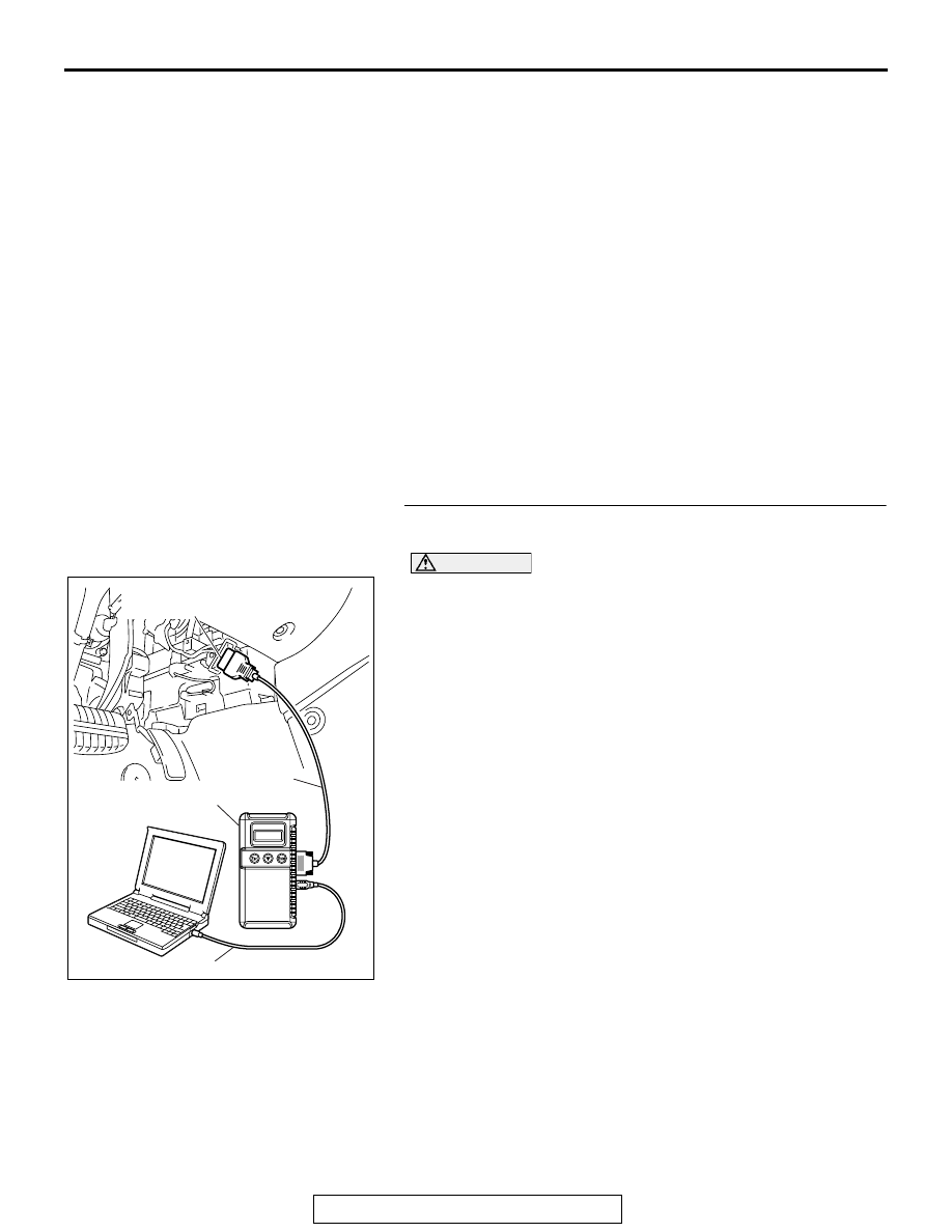
STEP 1. Using scan tool MB991958, diagnose the CAN bus 
line.

CAUTION

To prevent damage to scan tool MB991958, always turn the 
ignition switch to the "LOCK" (OFF) position before con-
necting or disconnecting scan tool MB991958.
(1) Connect scan tool MB991958. Refer to "How to connect the 

scan tool 

P.52B-30

."

(2) Connect scan tool MB991958 to the data link connector.
(3) Turn the ignition switch to "ON" position.
(4) Diagnose the CAN bus line.

Q: Is the check result satisfactory?

YES : Go to Step 2
NO :  Repair the CAN bus lines (Refer to GROUP 54C, 

Diagnosis-Can Bus Diagnostic Chart ).

AC305412

AB

MB991910

DATA LINK

CONNECTOR

MB991824

MB991827

SRS AIR BAG DIAGNOSIS

TSB Revision

SUPPLEMENTAL RESTRAINT SYSTEM (SRS)

52B-155

STEP 2. Recheck for diagnostic trouble code.
Check again if the DTC is set.
(1) Erase the DTC.
(2) Turn the ignition switch to "ON" position.
(3) Check if the DTC is set.
(4) Turn the ignition switch to the "LOCK" (OFF) position.

Q: Is the DTC set?

YES : Go to Step 3.
NO :  There is an intermittent malfunction such as poor 

engaged connector(s) or open circuit (Refer to 
GROUP 00, How to Use Troubleshooting/Inspection 
Service Points 

− How to Cope with Intermittent 

Malfunctions ).

STEP 3. Using scan tool MB991958, read the diagnostic 
trouble code.

CAUTION

To prevent damage to scan tool MB991958, always turn the 
ignition switch to the "LOCK" (OFF) position before con-
necting or disconnecting scan tool MB991958.
(1) Turn the ignition switch to the "ON" position.
(2) Check if the DTC is set.
(3) Turn the ignition switch to the "LOOK (OFF)" position.

Q: Is DTC B1519 set?

YES : Go to Step 4.
NO :  Go to Step 5.

AC305412

AB

MB991910

DATA LINK

CONNECTOR

MB991824

MB991827

AC305412

AB

MB991910

DATA LINK

CONNECTOR

MB991824

MB991827

SRS AIR BAG DIAGNOSIS

TSB Revision

SUPPLEMENTAL RESTRAINT SYSTEM (SRS)

52B-156

STEP 4. Check SRS-ECU connector C-122.
Q: Is the connector correctly engaged?

YES : Go to Step 5.
NO :  Engage the connector correctly. Then go to Step 9.

STEP 5. Check SRS-ECU connector C-122 and side-airbag 
module (LH) connector D-24. (Using scan tool MB991958, 
read the diagnostic trouble code.)
(1) Disconnect the negative battery terminal.
(2) Disconnect connectors C-122 and D-24, and then 

reconnect them.

(3) Connect the negative battery terminal.
(4) Erase the diagnostic trouble code memory, and check the 

diagnostic trouble code.

Q: Is DTC B1430 out put?

YES : Go to Step 6.
NO :  The procedure is complete. It is assumed that DTC 

B1430 set because connector C-122 or D-24 was 
engaged improperly.

AC305362

CONNECTOR: C-122

C-122 (Y)

AI

SRS-ECU

C-122 
Harness side
connector 
(rear view)

A

B

18

10

15

7

13

5

14

6

16

8

17

9

19

11

20

12

1 2

3 4

AC305362

CONNECTOR: C-122

C-122 (Y)

AI

SRS-ECU

C-122 
Harness side
connector 
(rear view)

A

B

18

10

15

7

13

5

14

6

16

8

17

9

19

11

20

12

1 2

3 4

AC307778

CONNECTOR : D-24

AC

D-24 (R)

2

1

HARNESS SIDE
CONNECTOR
(REAR VIEW)

SRS AIR BAG DIAGNOSIS

TSB Revision

SUPPLEMENTAL RESTRAINT SYSTEM (SRS)

52B-157

STEP 6. Check the side-airbag module (LH). (Using scan 
tool MB991958, read the diagnostic trouble code.)
(1) Disconnect the negative battery terminal.
(2) Disconnect the side-airbag module (LH) connector D-24.

(3) Connect special tool MB991865 to special tool MB991866.

CAUTION

Do not insert a test probe into the terminal from its front 
side directly, as the connector contact pressure may be 
weakened.
(4) Insert special tool MB991866 into the D-24 harness side 

connector by backprobing.

(5) Connect the negative battery terminal.
(6) Erase diagnostic trouble code memory, and check the 

diagnostic trouble code. 

Q: Is DTC B1430 set?

YES : Go to Step 7.
NO :  Replace the seatback frame of the front seat (LH) 

(Refer to GROUP 52A, Front Seat 

P.52A-25

). The

go to Step 9.

AC307778

CONNECTOR : D-24

AC

D-24 (R)

2

1

HARNESS SIDE
CONNECTOR
(REAR VIEW)

AC006042 BP

MB991866
(RESISTOR HARNESS)

D-24 HARNESS SIDE
CONNECTOR

D-24 SIDE-AIRBAG 
MODULE (LH) CONNECTOR

MB991865 (DUMMY 
RESISTOR: 3


)


Content   ..  1434  1435  1436  1437   ..