Mitsubishi Galant 9G. Manual - part 1366


  Index      Mitsubishi     Mitsubishi Galant 9G - service repair manual


Search            


Content   ..  1364  1365  1366  1367   ..


Mitsubishi Galant 9G. Manual - part 1366


DIAGNOSIS

TSB Revision

CONTROLLER AREA NETWORK (CAN)

54C-568

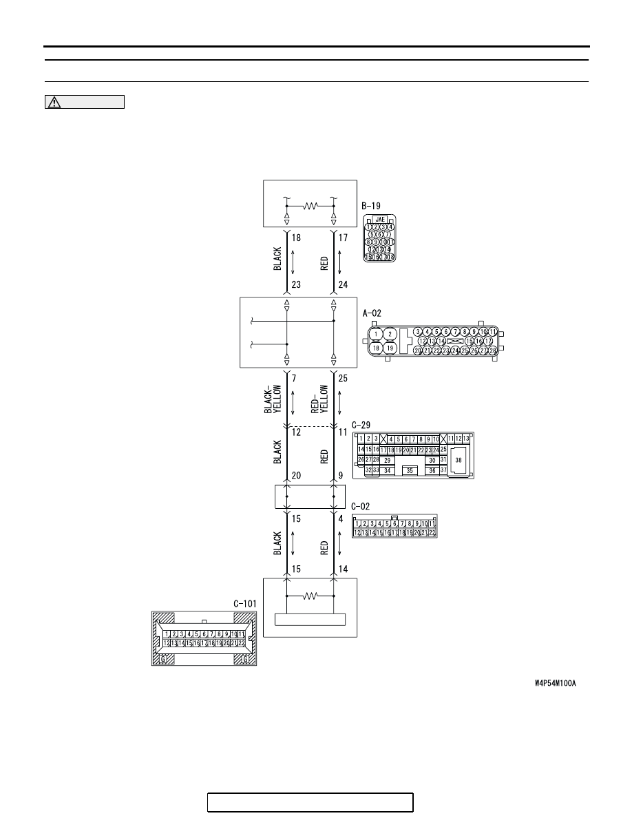
DIAGNOSTIC ITEM 19: Diagnose the lines between CAN main bus line and the ABS-ECU.

CAUTION

When servicing a CAN bus line, ground yourself 
by touching a metal object such as an unpainted 
water pipe. If you fail to do so, a component con-
nected to the CAN bus line may be damaged.

POWERTRAIN
CONTROL MODULE

ABS-ECU

JOINT
CONNECTOR (3)

COMBINATION
METER

DIAGNOSIS

TSB Revision

CONTROLLER AREA NETWORK (CAN)

54C-569

.

TROUBLE JUDGMENT

If the MUT-III cannot received signals from 
ABS-ECU, CAN bus line connector(s) are broken or 
an open circuit has occurred.

.

COMMENTS ON TROUBLE SYMPTOM

The wiring harness wire or connectors may have 
loose, corroded, or damage terminals, or terminals 
pushed back in the connector, or the ABS-ECU may 
be defective.

.

TROUBLESHOOTING HINTS

• The wiring harness or connectors may have 

loose, corroded, or damage terminals, or termi-
nals pushed back in the connector

• The ABS-ECU may be defective

AC305206

CONNECTOR: A-02

AR

A-02 (GR)

AC305231AX

CONNECTORS: C-02, C-29

C-02

C-29

DIAGNOSIS

TSB Revision

CONTROLLER AREA NETWORK (CAN)

54C-570

DIAGNOSIS

Required Special Tools:

• MB991223: Harness Set

• MB991970: ABS Check Harness

STEP 1. Check intermediate connector C-29 and ABS-ECU 
connector A-02 for loose, corroded or damaged terminals, 
or terminals pushed back in the connector.

CAUTION

The strand end of the twisted wire should be within 10 cm 
(4 inches) from the connector. For details refer to 

P.54C-4

.

Q: Are intermediate connector C-29 and ABS-ECU 

connector A-02 in good condition?
YES : 
Go to Step 2.
NO :  Repair the damaged parts. Replace the joint 

connector as necessary.

AC305206

CONNECTOR: A-02

AG

A-02 (GR)

HARNESS SIDE

AC305231AI

CONNECTOR: C-29

DIAGNOSIS

TSB Revision

CONTROLLER AREA NETWORK (CAN)

54C-571

STEP 2. Check the CAN bus lines between intermediate 
connector C-29 and the ABS-ECU. Measure the resistance 
between intermediate connector C-29 and ABS-ECU 
connector A-02.

CAUTION

A digital multimeter should be used. For details refer to 

P.54C-4

.

CAUTION

The test wiring harness should be used. For details refer to 

P.54C-4

.

(1) Disconnect intermediate connector C-29 and ABS-ECU 

connector A-02, and measure the resistance between the 
wiring harness side connector of ABS-ECU connector A-02 
and the male side connector of intermediate connector 
C-29 (at front wiring harness side).

(2) Turn the ignition switch to the "LOCK" (OFF) position.

CAUTION

Disconnect the negative battery terminal. For details refer 
to 

P.54C-4

.

(3) Disconnect the negative battery terminal.

AC305206

CONNECTOR: A-02

AG

A-02 (GR)

HARNESS SIDE

AC305231AI

CONNECTOR: C-29


Content   ..  1364  1365  1366  1367   ..