Mitsubishi Galant 9G. Manual - part 1365


  Index      Mitsubishi     Mitsubishi Galant 9G - service repair manual


Search            


Content   ..  1363  1364  1365  1366   ..


Mitsubishi Galant 9G. Manual - part 1365


DIAGNOSIS

TSB Revision

CONTROLLER AREA NETWORK (CAN)

54C-564

DIAGNOSIS

Required Special Tools:

• MB991223: Harness Set

• MB991970: ABS Check Harness

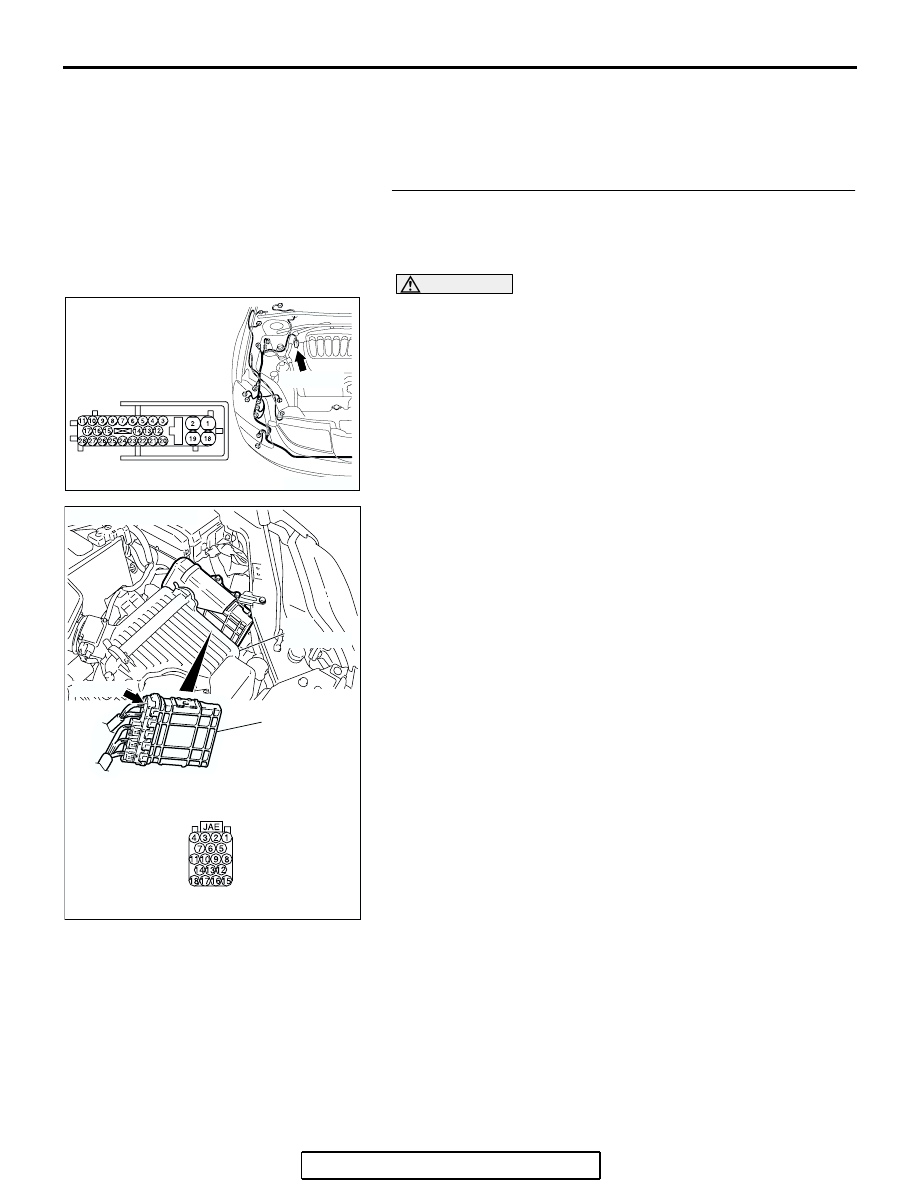
STEP 1. Check ABS-ECU connector A-02 and powertrain 
control module connector B-19 for  loose, corroded or 
damaged terminals, or terminals pushed back in the 
connector.

CAUTION

The strand end of the twisted wire should be within 10 cm 
(4 inches) from the connector. For details refer to 

P.54C-4

.

Q: Are ABS-ECU connector A-02 and powertrain control 

module connector B-19 in  good condition? 
YES : 
Go to Step 2.
NO :  Repair the damaged parts.

AC305206

CONNECTOR: A-02

AG

A-02 (GR)

HARNESS SIDE

AC306248AD

B-19 (B)

CONNECTOR: B-19

PCM

AIR
CLEANER

HARNESS SIDE

DIAGNOSIS

TSB Revision

CONTROLLER AREA NETWORK (CAN)

54C-565

STEP 2. Check the CAN bus lines between the ABS-ECU 
and the powertrain control module. Measure the resistance 
between ABS-ECU connector A-02 and powertrain control 
module connector B-19.

CAUTION

A digital multimeter should be used. For details refer to 

P.54C-4

.

CAUTION

The test wiring harness should be used. For details refer to 

P.54C-4

.

(1) Disconnect ABS-ECU connector A-02 and powertrain 

control module connector B-19, and measure the resistance 
between each wiring harness side connector.

(2) Turn the ignition switch to the "LOCK" (OFF) position.

CAUTION

Disconnect the negative battery terminal. For details refer 
to 

P.54C-4

.

(3) Disconnect the negative battery terminal.

AC305206

CONNECTOR: A-02

AG

A-02 (GR)

HARNESS SIDE

AC306248AD

B-19 (B)

CONNECTOR: B-19

PCM

AIR
CLEANER

HARNESS SIDE

DIAGNOSIS

TSB Revision

CONTROLLER AREA NETWORK (CAN)

54C-566

(4) Measure the resistance between ABS-ECU connector 

terminal 23 and powertrain control module connector 
terminal 18.

OK: 2 ohms or less

(5) Measure the resistance between ABS-ECU connector 

terminal 24 and powertrain control module connector 
terminal 17.

OK: 2 ohms or less

CAUTION

Strictly observe the specified wiring harness repair proce-
dure. For details refer to 

P.54C-5

.

Q: Do all the resistances measure 2 ohms or less?

YES : If all the resistances measure 2 ohms or less, go to 

Step 3.

NO :  If either of the resistances measures more than 2 

ohms or all the resistances measure more than 2 
ohms, repair the wiring harness between ABS-ECU 
connector and the powertrain control module 
connector. 

AC204582

HARNESS SIDE: A-02

HARNESS SIDE: B-19

TEST 
HARNESS

TEST 
HARNESS

3

17

10

13

18

4

11

14

7

16 15

1

2

5

12

9

6

8

JAE

19

18

2

1

25

8

15

16

17

27

28

26

11

9

10

12

13

14

23

24

22 21

7

6

5

4

20

3

CU

AC204582

3

17

10

13

18

4

11

14

7

16 15

1

2

5

12

9

6

8

JAE

19

18

2

1

25

8

15

16

17

27

28

26

11

9

10

12

13

14

23

24

22 21

7

6

5

4

20

3

HARNESS SIDE: A-02

HARNESS SIDE: B-19

TEST 
HARNESS

TEST 
HARNESS

CT

DIAGNOSIS

TSB Revision

CONTROLLER AREA NETWORK (CAN)

54C-567

STEP 3. Check the CAN bus lines inside the ABS-ECU. 
Measure the resistance at ABS-ECU connector A-02.

CAUTION

A digital multimeter should be used. For details refer to 

P.54C-4

.

CAUTION

The test wiring harness should be used. For details refer to 

P.54C-4

.

(1) Disconnect ABS-ECU connector A-02, and measure the 

resistance at the component side of ABS-ECU connector 
A-02.

(2) Turn the ignition switch to the "LOCK" (OFF) position.

CAUTION

Disconnect the negative battery terminal. For details refer 
to 

P.54C-4

.

(3) Disconnect the negative battery terminal.

(4) Measure the resistance between ABS-ECU connector 

terminals 7 and 23.

OK: 2 ohms or less

(5) Measure the resistance between ABS-ECU connector 

terminals 24 and 25.

OK: 2 ohms or less

CAUTION

Strictly observe the specified wiring harness repair proce-
dure. For details refer to 

P.54C-5

.

Q: Do all the resistances measure 2 ohms or less?

YES : If all the resistances measure 2 ohms or less, power 

supply to the powertrain control module may be 
suspected. Diagnose the engine. Refer to GROUP 
13A, MFI diagnosis 

P.13A-970

 <2.4L engine> or 

GROUP 13B, MFI diagnosis 

P.13B-1016

 <3.8L 

engine>.

NO :  If either of the resistances measures more than 2 

ohms or all the resistances measure more than 2 
ohms, replace the ABS-ECU.

AC305206

CONNECTOR: A-02

AG

A-02 (GR)

HARNESS SIDE

AC209438

COMPONENT SIDE: A-02

TEST 
HARNESS

AC

TEST 
HARNESS

AC209438

COMPONENT SIDE: A-02

AD

TEST 
HARNESS

TEST 
HARNESS


Content   ..  1363  1364  1365  1366   ..