Mitsubishi Galant 9G. Manual - part 1353


  Index      Mitsubishi     Mitsubishi Galant 9G - service repair manual


Search            


Content   ..  1351  1352  1353  1354   ..


Mitsubishi Galant 9G. Manual - part 1353


DIAGNOSIS

TSB Revision

CONTROLLER AREA NETWORK (CAN)

54C-516

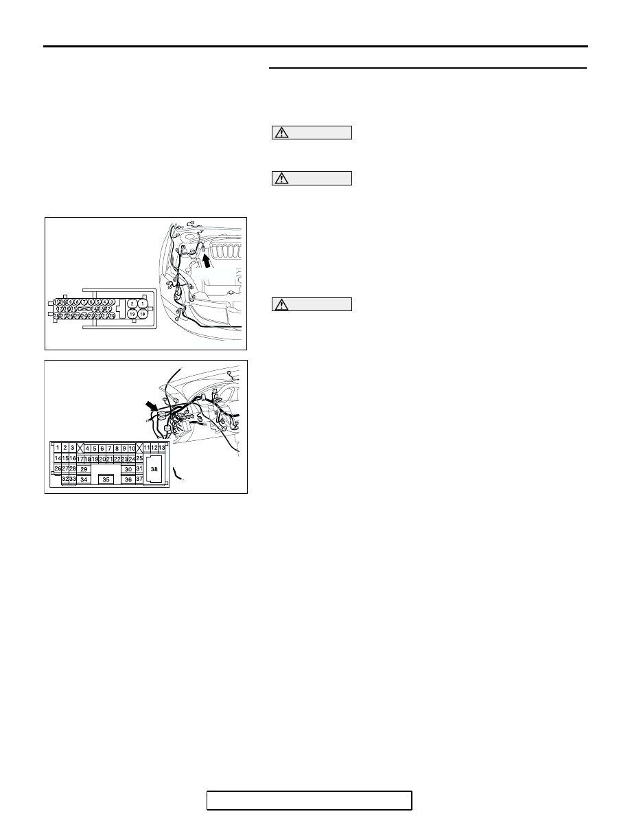
STEP 25. Check the CAN bus lines between intermediate 
connector C-29 and the ABS-ECU. Measure the resistance 
between intermediate connector C-29 and ABS-ECU 
connector A-02.

CAUTION

A digital multimeter should be used. For details refer to 

P.54C-4

.

CAUTION

The test wiring harness should be used. For details refer to 

P.54C-4

.

(1) Disconnect intermediate connector C-29 and ABS-ECU 

connector A-02, and measure the resistance between the 
wiring harness side connector of ABS-ECU connector A-02 
and the male side connector of intermediate connector 
C-29 (at front wiring harness side).

(2) Turn the ignition switch to the "LOCK" (OFF) position.

CAUTION

Disconnect the negative battery terminal. For details refer 
to 

P.54C-4

.

(3) Disconnect the negative battery terminal.

AC305206

CONNECTOR: A-02

AG

A-02 (GR)

HARNESS SIDE

AC305231AI

CONNECTOR: C-29

DIAGNOSIS

TSB Revision

CONTROLLER AREA NETWORK (CAN)

54C-517

(4) Measure the resistance between intermediate connector 

terminal 11 and ABS-ECU connector terminal 25.

OK: 2 ohms or less

(5) Measure the resistance between intermediate connector 

terminal 12 and ABS-ECU connector terminal 7.

OK: 2 ohms or less

CAUTION

Strictly observe the specified wiring harness repair proce-
dure. For details refer to 

P.54C-5

.

Q: Do all the resistances measure 2 ohms or less?

YES  : If all the resistances measure 2 ohms or less, go to 

Step 26.

NO  : If either of the resistances measures more than 2 

ohms or all the resistances measure more than 2 
ohms, repair the wiring harness between intermediate 
connector C-29 and the ABS-ECU connector. 

AC204582

2 3

27

32

28

33

16

15

4 5

19

18

29

17

34

7 8

35

22

21

9 10

30

36

31

37

25

24

23

6

20

1

14

26

11

13

12

38

AC204582

TEST 
HARNESS

19

18

2

1

25

8

15

16

17

27

28

26

11

9

10

12

13

14

23

24

22 21

7

6

5

4

20

3

TEST 
HARNESS

HARNESS SIDE: A-02

CP

MALE SIDE: C-29

AC204582

AC204582

19

18

2

1

25

8

15

16

17

27

28

26

11

9

10

12

13

14

23

24

22 21

7

6

5

4

20

3

TEST HARNESS

TEST 
HARNESS

CO

HARNESS SIDE: A-02

2 3

27

32

28

33

16

15

4 5

19

18

29

17

34

7 8

35

22

21

9 10

30

36

31

37

25

24

23

6

20

1

14

26

11

13

12

38

MALE SIDE: C-29

DIAGNOSIS

TSB Revision

CONTROLLER AREA NETWORK (CAN)

54C-518

STEP 26. Check the CAN bus lines between intermediate 
connector C-29 and the joint connector (3). Measure the 
resistance between intermediate connector C-29 and joint 
connector (3) C-02.

CAUTION

A digital multimeter should be used. For details refer to 

P.54C-4

.

CAUTION

The test wiring harness should be used. For details refer to 

P.54C-4

.

(1) Disconnect joint connector (3) C-02 and intermediate 

connector C-29, and measure the resistance between the 
wiring harness side connector of joint connector (3) C-02 
and the female side connector of intermediate connector 
C-29 (instrument panel wiring harness side).

(2) Turn the ignition switch to the "LOCK" (OFF) position.

CAUTION

Disconnect the negative battery terminal. For details refer 
to 

P.54C-4

.

(3) Disconnect the negative battery terminal.

AC305232

CONNECTORS: C-02, C-29

AG

C-02

C-02

C-29

C-29

DIAGNOSIS

TSB Revision

CONTROLLER AREA NETWORK (CAN)

54C-519

(4) Measure the resistance between intermediate connector 

terminal 11 and joint connector (3) terminal 9.

OK: 2 ohms or less

(5) Measure the resistance between intermediate connector 

terminal 12 and joint connector (3) terminal 20.

OK: 2 ohms or less

CAUTION

Strictly observe the specified wiring harness repair proce-
dure. For details refer to 

P.54C-5

.

Q: Do all the resistances measure 2 ohms or less?

YES  : If all the resistances measure 2 ohms or less, power 

supply to the ABS-ECU may be suspected. Diagnose 
the ABS system. Refer to GROUP 35B, ABS 
diagnosis 

P.35B-82

.

NO  : If either of the resistances measures more than 2 

ohms or all the resistances measure more than 2 
ohms, repair the wiring harness between joint 
connector (3) and intermediate connector C-29. 

AC204582

35

34

36

30

38

29

17

13 12 11

37

31

33 32

26

27

28

16

14

15

3 2

4

18

6

7

21 20

5

19

9

10

24 23

25

8

22

1

TEST 
HARNESS

FEMALE SIDE: C-29

HARNESS SIDE: C-02

TEST 
HARNESS

11

22

10

21

9

20

8

19

7

18

6

17

5

16

4

15

3

14

2

13

1

12

CQ

AC204582

35

34

36

30

38

29

17

13 12 11

37

31

33 32

26

27

28

16

14

15

3 2

4

18

6

7

21 20

5

19

9

10

24 23

25

8

22

1

TEST 
HARNESS

FEMALE SIDE: C-29

HARNESS SIDE: C-02

TEST 
HARNESS

11

22

10

21

9

20

8

19

7

18

6

17

5

16

4

15

3

14

2

13

1

12

CR


Content   ..  1351  1352  1353  1354   ..