Mitsubishi Galant 9G. Manual - part 1351


  Index      Mitsubishi     Mitsubishi Galant 9G - service repair manual


Search            


Content   ..  1349  1350  1351  1352   ..


Mitsubishi Galant 9G. Manual - part 1351


DIAGNOSIS

TSB Revision

CONTROLLER AREA NETWORK (CAN)

54C-508

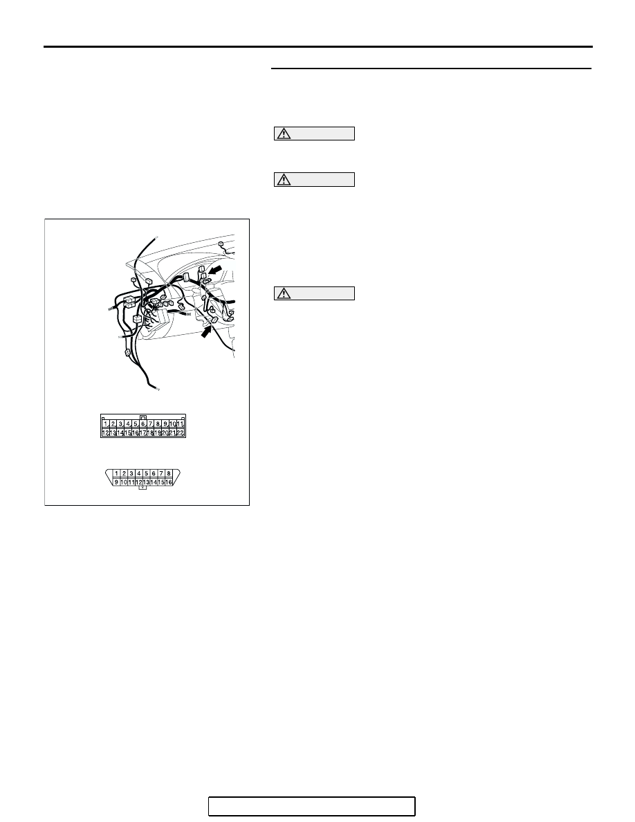
STEP 19. Check the CAN bus lines between joint 
connector (3) and the data link connector. Measure the 
resistance between joint connector (3) C-02 and data link 
connector C-125.

CAUTION

A digital multimeter should be used. For details refer to 

P.54C-4

.

CAUTION

The test wiring harness should be used. For details refer to 

P.54C-4

.

(1) Disconnect joint connector (3) C-02, and measure the 

resistance between the wiring harness side connector of 
joint connector (3) C-02 and wiring harness side connector 
of data link connector C-125.

(2) Turn the ignition switch to the "LOCK" (OFF) position.

CAUTION

Disconnect the negative battery terminal. For details refer 
to 

P.54C-4

.

(3) Disconnect the negative battery terminal.

AC305232

C-125

CONNECTORS: C-02, C-125

AF

C-02

C-02

C-125 (B)

DIAGNOSIS

TSB Revision

CONTROLLER AREA NETWORK (CAN)

54C-509

(4) Measure the resistance between joint connector (3) 

terminal 18 and data link connector terminal 14.

OK: 2 ohms or less

(5) Measure the resistance between joint connector (3) 

terminal 7 and data link connector terminal 6.

OK: 2 ohms or less

CAUTION

Strictly observe the specified wiring harness repair proce-
dure. For details refer to 

P.54C-5

.

Q: Do all the resistances measure 2 ohms or less?

YES  : If all the resistances measure 2 ohms or less, refer to 

diagnostics item 8: Check the CAN_L and H lines for 
a short circuit (Refer to 

P.54C-331

).

NO :  If all the resistances measure 2 ohms or less, repair 

the wiring harness between joint connector (3) and 
the data link connector.

AC204582DI

11

22

10

21

9

20

8

19

7

18

6

17

5

16

4

15

3

14

2

13

1

12

TEST 
HARNESS

HARNESS SIDE: C-02

TEST 
HARNESS

Y

8

16

15

7

5

1314

6

12

4

2

1011

3

9

1

HARNESS SIDE: C-125

AC204582

HARNESS SIDE: C-02

TEST 
HARNESS

DH

11

22

10

21

9

20

8

19

7

18

6

17

5

16

4

15

3

14

2

13

1

12

Y

8

16

15

7

5

1314

6

12

4

2

1011

3

9

1

TEST 
HARNESS

HARNESS SIDE: C-125

DIAGNOSIS

TSB Revision

CONTROLLER AREA NETWORK (CAN)

54C-510

STEP 20. Check ABS-ECU connector A-02 and powertrain 
control module connector B-19 for  loose, corroded or 
damaged terminals, or terminals pushed back in the 
connector.

CAUTION

The strand end of the twisted wire should be within 10 cm 
(4 inches) from the connector. For details refer to 

P.54C-4

.

Q: Are ABS-ECU connector A-02 and powertrain control 

module connector B-19 in  good condition? 
YES : 
Go to Step 21.
NO :  Repair the damaged parts.

AC305206

CONNECTOR: A-02

AG

A-02 (GR)

HARNESS SIDE

AC306248AD

B-19 (B)

CONNECTOR: B-19

PCM

AIR
CLEANER

HARNESS SIDE

DIAGNOSIS

TSB Revision

CONTROLLER AREA NETWORK (CAN)

54C-511

STEP 21. Using scan tool MB991958, diagnose the CAN 
bus line (Disconnect powertrain control module connector 
B-19, and check the powertrain control module system).
(1) Disconnect powertrain control module connector B-19.
(2) Turn the ignition switch to the "ON" position.

(3) Diagnose CAN bus lines, and check if the MUT-III screen is 

as shown in the illustration.

(4) Turn the ignition switch to the "LOCK" (OFF) position.
(5) Connect powertrain control module connector B-19.
Q: Does the MUT-III screen correspond to the illustration?

YES  : If the MUT-III screen corresponds to the illustration, 

go to Step 22 .

NO  : If the MUT-III screen does not correspond to the 

illustration, go to Step 24.

AC306248AD

B-19 (B)

CONNECTOR: B-19

PCM

AIR
CLEANER

HARNESS SIDE

AC306074

: Red section on screen

AH

PCM

MUT

ETACS

-ECU

AC-ECU

SRS-ECU

ABS-ECU

J/C

METER

-ECU


Content   ..  1349  1350  1351  1352   ..