Mitsubishi Galant 9G. Manual - part 1301


  Index      Mitsubishi     Mitsubishi Galant 9G - service repair manual


Search            


Content   ..  1299  1300  1301  1302   ..


Mitsubishi Galant 9G. Manual - part 1301


DIAGNOSIS

TSB Revision

CONTROLLER AREA NETWORK (CAN)

54C-308

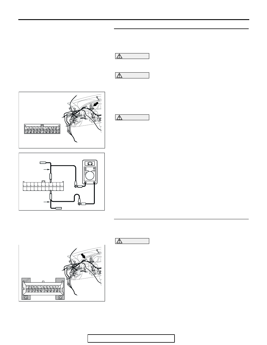
STEP 4. Check the CAN_L and H lines (communication 
lines including the combination meter) between joint 
connector (3) and the combination meter for a short 
circuit. Measure the resistance at joint connector (3) C-02.

CAUTION

A digital multimeter should be used. For details refer to 

P.54C-4

.

CAUTION

The test wiring harness should be used. For details refer to 

P.54C-4

.

(1) Disconnect joint connector (3) C-02, and measure the 

resistance at the wiring harness side of joint connector (3) 
C-02.

(2) Turn the ignition switch to the "LOCK" (OFF) position.

CAUTION

Disconnect the negative battery terminal. For details refer 
to 

P.54C-4

.

(3) Disconnect the negative battery terminal.

(4) Measure the resistance between joint connector (3) 

terminals 4 and 15.

OK: 120 

± 20 

Q: Does the resistance measure 120 

± 20 ?

YES : If the resistance measures 120 

± 20 Ω, go to Step 8.

NO :  If the resistance does not measure 120 

± 20 Ω> Go to 

Step 5.

STEP 5. Check combination meter connector C-101 for 
loose, corroded or damaged terminals, or terminals 
pushed back in the connector.

CAUTION

The strand end of the twisted wire should be within 10 cm 
(4 inches) from the connector. For details refer to 

P.54C-4

.

Q: Is combination meter connector C-101 in good 

condition?
YES : 
Go to Step 6.
NO :  Repair the damaged parts.

AC305231AP

CONNECTOR: C-02

AC209438

11

22

10

21

9

20

8

19

7

18

6

17

5

16

4

15

3

14

2

13

1

12

TEST 
HARNESS

AQ

TEST 
HARNESS

HARNESS SIDE: C-02

AC305231AQ

CONNECTOR: C-101

HARNESS SIDE

DIAGNOSIS

TSB Revision

CONTROLLER AREA NETWORK (CAN)

54C-309

STEP 6. Check the CAN_L and H lines (communication 
lines only) between joint connector (3) and the 
combination meter for a short circuit. Measure the 
resistance at joint connector (3) C-02.

CAUTION

A digital multimeter should be used. For details refer to 

P.54C-4

.

CAUTION

The test wiring harness should be used. For details refer to 

P.54C-4

.

(1) Disconnect joint connector (3) C-02 and combination meter 

connector C-101, and measure the resistance at the wiring 
harness side of joint connector (3) C-02.

(2) Turn the ignition switch to the "LOCK" (OFF) position.

CAUTION

Disconnect the negative battery terminal. For details refer 
to 

P.54C-4

.

(3) Disconnect the negative battery terminal.

(4) Measure the resistance between joint connector (3) 

terminals 4 and 15.

OK: 1 k

 or more

CAUTION

Strictly observe the specified wiring harness repair proce-
dure. For details refer to 

P.54C-5

.

Q: Does the resistance measure 1 k

 or more?

YES : If the resistance measures 1 k

Ω or more, go to Step 7  

.

NO :  If the resistance measures less than 1 k

Ω, repair the 

wiring harness between joint connector (3) and the 
combination meter connector.

AC305232

HARNESS SIDE

C-101

CONNECTORS: C-02, C-101

AE

C-02

C-02

C-101

AC209438

11

22

10

21

9

20

8

19

7

18

6

17

5

16

4

15

3

14

2

13

1

12

TEST 
HARNESS

AQ

TEST 
HARNESS

HARNESS SIDE: C-02

DIAGNOSIS

TSB Revision

CONTROLLER AREA NETWORK (CAN)

54C-310

STEP 7. Check the combination meter for a short circuit. 
Measure the resistance at combination meter connector 
C-101.

CAUTION

A digital multimeter should be used. For details refer to 

P.54C-4

.

(1) Disconnect combination meter C-101, and measure the 

resistance at the component side of combination meter 
connector C-101.

(2) Measure the resistance between combination meter 

connector terminals 14 and 15.

OK: 120 

± 20 

Q: Does the resistance measure 120 

± 20 ?

YES : If the resistance measures 120 

± 20 Ω, diagnose CAN 

bus lines thoroughly by referring to 

P.54C-456

.

NO :  If the resistance does not measure 120 

± 20 Ω, 

replace the combination meter.

AC305231AQ

CONNECTOR: C-101

HARNESS SIDE

AC204582BY

COMPONENT SIDE: C-101

G

11

22

17

3

14

G

12

1

13

2

15

4

16

5

18

7

6

19

8

10

21

20

9

TEST 
HARNESS

TEST HARNESS

DIAGNOSIS

TSB Revision

CONTROLLER AREA NETWORK (CAN)

54C-311

STEP 8. Check the CAN_L and H lines (communication 
lines including the ETACS-ECU) between joint connector 
(3) and the ETACS-ECU for a short circuit. Measure the 
resistance at joint connector (3) C-02.

CAUTION

A digital multimeter should be used. For details refer to 

P.54C-4

.

CAUTION

The test wiring harness should be used. For details refer to 

P.54C-4

.

(1) Disconnect joint connector (3) C-02, and measure the 

resistance at the wiring harness side of joint connector (3) 
C-02.

(2) Turn the ignition switch to the "LOCK" (OFF) position.

CAUTION

Disconnect the negative battery terminal. For details refer 
to 

P.54C-4

.

(3) Disconnect the negative battery terminal.

(4) Measure the resistance between joint connector (3) 

terminals 5 and 16.

OK: 1 k

 or more

Q: Does the resistance measure 1 k

 or more?

YES : If the resistance measures 1 k

Ω or more, go to Step 

12  .

NO :  If the resistance measures less than 1 k

Ω, go to Step 

9.

STEP 9. Check ETACS-ECU connector C-218 for loose, 
corroded or damaged terminals, or terminals pushed back 
in the connector.

CAUTION

The strand end of the twisted wire should be within 10 cm 
(4 inches) from the connector. For details refer to 

P.54C-4

.

Q: Is ETACS-ECU connector C-218 in good condition?

YES : Go to Step 10.
NO :  Repair the damaged parts.

AC305231AP

CONNECTOR: C-02

AC209438

TEST 
HARNESS

AR

TEST 
HARNESS

11

22

10

21

9

20

8

19

7

18

6

17

5

16

4

15

3

14

2

13

1

12

HARNESS SIDE: C-02

AC305413

C-218 (GR)

CONNECTOR: C-218

AI

HARNESS SIDE

JUNCTION BLOCK
(REAR VIEW)

68

74

63

66

72

73

67

65 64

61

70

71

62

69

60

57

58

59

56 55

52

54 53

51


Content   ..  1299  1300  1301  1302   ..