Mitsubishi Galant 9G. Manual - part 1299


  Index      Mitsubishi     Mitsubishi Galant 9G - service repair manual


Search            


Content   ..  1297  1298  1299  1300   ..


Mitsubishi Galant 9G. Manual - part 1299


DIAGNOSIS

TSB Revision

CONTROLLER AREA NETWORK (CAN)

54C-300

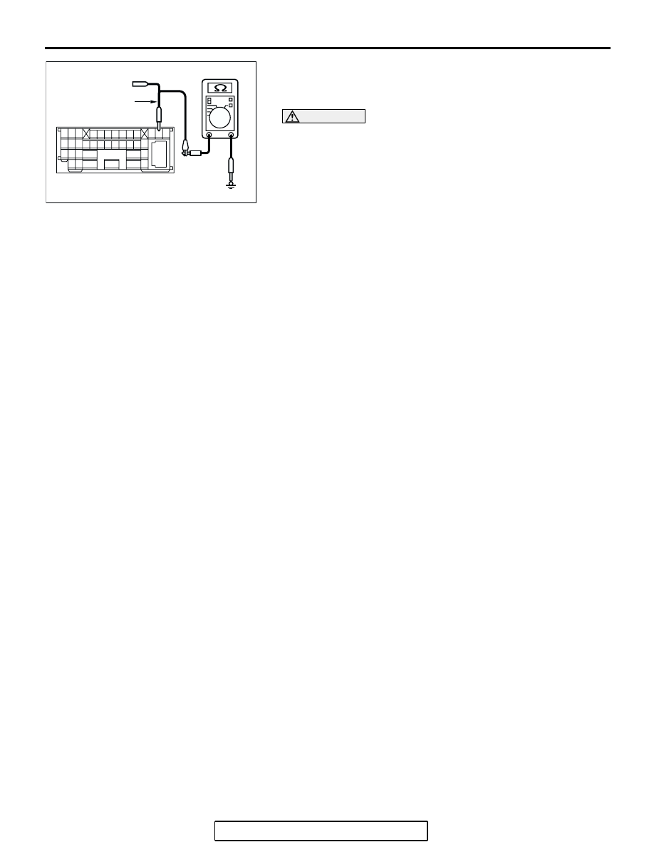
(4) Measure the resistance between intermediate connector 

terminal 12 and body ground.

OK: 1 k

 or more

CAUTION

Strictly observe the specified wiring harness repair proce-
dure. For details refer to 

P.54C-5

.

Q: Does the resistance measure 1 k

 or more?

YES : If the resistance measures 1 k

Ω or more, go to Step 

54   .

NO :  If the resistance measures less than 1 k

Ω, repair the 

wiring harness between intermediate connector C-29 
and ABS-ECU connector.

AC209364

2 3

27

32

28

33

16

15

4 5

19

18

29

17

34

7 8

35

22

21

9 10

30

36

31

37

25

24

23

6

20

1

14

26

11

13

12

38

MALE SIDE: C-29

TEST HARNESS

GA

DIAGNOSIS

TSB Revision

CONTROLLER AREA NETWORK (CAN)

54C-301

STEP 54. Check the CAN_L line (communication line only) 
between the powertrain control module  connector and 
ABS-ECU connector for short to ground. Measure the 
resistance at powertrain control module connector B-19.

CAUTION

A digital multimeter should be used. For details refer to 

P.54C-4

.

CAUTION

The test wiring harness should be used. For details refer to 

P.54C-4

.

(1) Disconnect powertrain control module connector B-19 and 

ABS-ECU connector A-02, and measure the resistance at 
the harness side of powertrain control module connector 
B-19.

(2) Turn the ignition switch to the "LOCK" (OFF) position.

CAUTION

Disconnect the negative battery terminal. For details refer 
to 

P.54C-4

.

(3) Disconnect the negative battery terminal.

AC305206

CONNECTOR: A-02

AG

A-02 (GR)

HARNESS SIDE

AC306248AD

B-19 (B)

CONNECTOR: B-19

PCM

AIR
CLEANER

HARNESS SIDE

DIAGNOSIS

TSB Revision

CONTROLLER AREA NETWORK (CAN)

54C-302

(4) Measure the resistance between powertrain control module 

connector terminal 18 and body ground.

OK: 1 k

 or more

CAUTION

Strictly observe the specified wiring harness repair proce-
dure. For details refer to 

P.54C-5

.

Q: Does the resistance measure 1 k

 or more?

YES : If the resistance measures 1 k

Ω or more, go to Step 

55   .

NO :  If the resistance measures less than 1 k

Ω, repair the 

wiring harness between powertrain control module 
connector and ABS-ECU connector.

STEP 55. Check the CAN_L line inside the ABS-ECU for 
short to ground. Measure the resistance at ABS-ECU 
connector A-02.

CAUTION

A digital multimeter should be used. For details refer to 

P.54C-4

.

CAUTION

The test wiring harness should be used. For details refer to 

P.54C-4

.

(1) Disconnect ABS-ECU connector A-02.

AC209364IP

HARNESS SIDE: B-19

TEST HARNESS

AC305206

CONNECTOR: A-02

AG

A-02 (GR)

HARNESS SIDE

DIAGNOSIS

TSB Revision

CONTROLLER AREA NETWORK (CAN)

54C-303

(2) Connect special tool MB991970 (ABS check harness) to 

the ABS-ECU and the wiring harness, and measure the 
resistance at special tool MB991970 (ABS check harness).

(3) Turn the ignition switch to the "LOCK" (OFF) position.

CAUTION

Disconnect the negative battery terminal. For details refer 
to 

P.54C-4

.

(4) Disconnect the negative battery terminal.
(5) Measure the resistance between special tool MB991970 

(ABS check harness) connector terminal 7 and body 
ground.

OK: 1 k

 or more

Q: Does the resistance measure 1 k

 or more?

YES : If the resistance measures 1 k

Ω or more, diagnose 

CAN bus lines thoroughly by referring to 

P.54C-520

.

NO :  If the resistance measures less than 1 k

Ω, replace the 

ABS-ECU.

AC209767

TEST 
HARNESS

2

19

1

18

25

8

15

16

17

27

28

26

11

9

10

12

13

14

23

24

22 21

7

6

5

4

20

3

SPECIAL TOOL
MB991970

ABS-
ECU

SPECIAL TOOL MB991970 
CONNECTOR

AD

MEASUREMENT CONNECTOR


Content   ..  1297  1298  1299  1300   ..