Mitsubishi Galant 9G. Manual - part 1298


  Index      Mitsubishi     Mitsubishi Galant 9G - service repair manual


Search            


Content   ..  1296  1297  1298  1299   ..


Mitsubishi Galant 9G. Manual - part 1298


DIAGNOSIS

TSB Revision

CONTROLLER AREA NETWORK (CAN)

54C-296

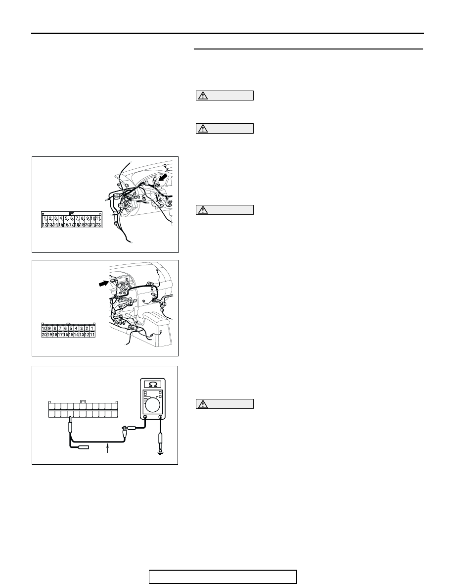
STEP 49. Check the CAN_L line (communication line only) 
between joint connector (3) and multi-center display unit 
(middle-grade type) connector  for short to ground. 
Measure the resistance at joint connector (3) C-02.

CAUTION

A digital multimeter should be used. For details refer to 

P.54C-4

.

CAUTION

The test wiring harness should be used. For details refer to 

P.54C-4

.

(1) Disconnect joint connector (3) C-02 and multi-center display 

unit (middle-grade type) connector C-05, and measure the 
resistance at the wiring harness side of joint connector (3) 
C-02.

(2) Turn the ignition switch to the "LOCK" (OFF) position.

CAUTION

Disconnect the negative battery terminal. For details refer 
to 

P.54C-4

.

(3) Disconnect the negative battery terminal.

(4) Measure the resistance between joint connector (3) 

terminal 19 and body ground.

OK: 1 k

 or more

CAUTION

Strictly observe the specified wiring harness repair proce-
dure. For details refer to 

P.54C-5

.

Q: Does the resistance measure 1 k

 or more?

YES : If the resistance measures 1 k

Ω or more, diagnose 

CAN bus lines thoroughly by referring to 

P.54C-520

.

NO :  If the resistance measures less than 1 k

Ω, repair the 

wiring harness between joint connector (3) and 
multi-center display unit (middle-grade type) 
connector.

AC305231AP

CONNECTOR: C-02

AC305233 AF

CONNECTOR: C-05

HARNESS SIDE

C-05 (B)

AC209364JI

11

22

10

21

9

20

8

19

7

18

6

17

5

16

4

15

3

14

2

13

1

12

HARNESS SIDE: C-02

TEST HARNESS

DIAGNOSIS

TSB Revision

CONTROLLER AREA NETWORK (CAN)

54C-297

STEP 50. Check the CAN_L line (communication line only) 
between joint connector (3) and the data link connector for 
short to ground. Measure the resistance at joint connector 
(3) C-02.

CAUTION

A digital multimeter should be used. For details refer to 

P.54C-4

.

CAUTION

The test wiring harness should be used. For details refer to 

P.54C-4

.

(1) Disconnect joint connector (3) C-02, and measure the 

resistance at the wiring harness side of joint connector (3) 
C-02.

(2) Turn the ignition switch to the "LOCK" (OFF) position.

CAUTION

Disconnect the negative battery terminal. For details refer 
to 

P.54C-4

.

(3) Disconnect the negative battery terminal.

(4) Measure the resistance between joint connector (3) 

terminal 18 and body ground.

OK: 1 k

 or more

CAUTION

Strictly observe the specified wiring harness repair proce-
dure. For details refer to 

P.54C-5

.

Q: Does the resistance measure 1 k

 or more?

YES : If the resistance measures 1 k

Ω or more, go to Step 

51   .

NO :  If the resistance measures less than 1 k

Ω, repair the 

wiring harness between joint connector (3) and the 
data link connector.

AC305231AP

CONNECTOR: C-02

AC209364IM

11

22

10

21

9

20

8

19

7

18

6

17

5

16

4

15

3

14

2

13

1

12

HARNESS SIDE: C-02

TEST HARNESS

DIAGNOSIS

TSB Revision

CONTROLLER AREA NETWORK (CAN)

54C-298

STEP 51. Check the CAN_L line (communication line only) 
between intermediate connector C-29 and joint connector 
(3) for  short to ground. Measure the resistance at joint 
connector (3) C-02.

CAUTION

A digital multimeter should be used. For details refer to 

P.54C-4

.

CAUTION

The test wiring harness should be used. For details refer to 

P.54C-4

.

(1) Disconnect intermediate connector C-29 and joint 

connector (3) C-02, and measure the resistance at the 
wiring harness side of joint connector (3) C-02.

(2) Turn the ignition switch to the "LOCK" (OFF) position.

CAUTION

Disconnect the negative battery terminal. For details refer 
to 

P.54C-4

.

(3) Disconnect the negative battery terminal.

(4) Measure the resistance between joint connector (3) 

terminal 20 and body ground.

OK: 1 k

 or more

CAUTION

Strictly observe the specified wiring harness repair proce-
dure. For details refer to 

P.54C-5

.

Q: Does the resistance measure 1 k

 or more?

YES : If the resistance measures 1 k

Ω or more, diagnose 

CAN bus lines thoroughly by referring to 

P.54C-520

.

NO :  If the resistance measures less than 1 k

Ω, repair the 

wiring harness between intermediate connector C-29 
and joint connector (3).

AC305232

CONNECTORS: C-02, C-29

AG

C-02

C-02

C-29

C-29

AC209364IO

11

22

10

21

9

20

8

19

7

18

6

17

5

16

4

15

3

14

2

13

1

12

HARNESS SIDE: C-02

TEST HARNESS

DIAGNOSIS

TSB Revision

CONTROLLER AREA NETWORK (CAN)

54C-299

STEP 52. Check ABS-ECU connector A-02 for loose, 
corroded or damaged terminals, or terminals pushed back 
in the connector.

CAUTION

The strand end of the twisted wire should be within 10 cm 
(4 inches) from the connector. For details refer to 

P.54C-4

.

Q: Is ABS-ECU connector A-02 in good condition?

YES : Go to Step 53.
NO :  Repair the damaged parts.

STEP 53. Check the CAN_L line (communication line only) 
between intermediate connector C-29 and ABS-ECU 
connector for short to ground. Measure the resistance at 
intermediate connector C-29.

CAUTION

A digital multimeter should be used. For details refer to 

P.54C-4

.

CAUTION

The test wiring harness should be used. For details refer to 

P.54C-4

.

(1) Disconnect intermediate connector C-29 and ABS-ECU 

connector A-02, and measure the resistance at the male 
side of intermediate connector C-29 (at front wiring harness 
side).

(2) Turn the ignition switch to the "LOCK" (OFF) position.

CAUTION

Disconnect the negative battery terminal. For details refer 
to 

P.54C-4

.

(3) Disconnect the negative battery terminal.

AC305206

CONNECTOR: A-02

AG

A-02 (GR)

HARNESS SIDE

AC305206

CONNECTOR: A-02

AG

A-02 (GR)

HARNESS SIDE

AC305231AI

CONNECTOR: C-29


Content   ..  1296  1297  1298  1299   ..