Content .. 1290 1291 1292 1293 ..
Mitsubishi Galant 9G. Manual - part 1292
DIAGNOSIS
TSB Revision
CONTROLLER AREA NETWORK (CAN)
54C-272
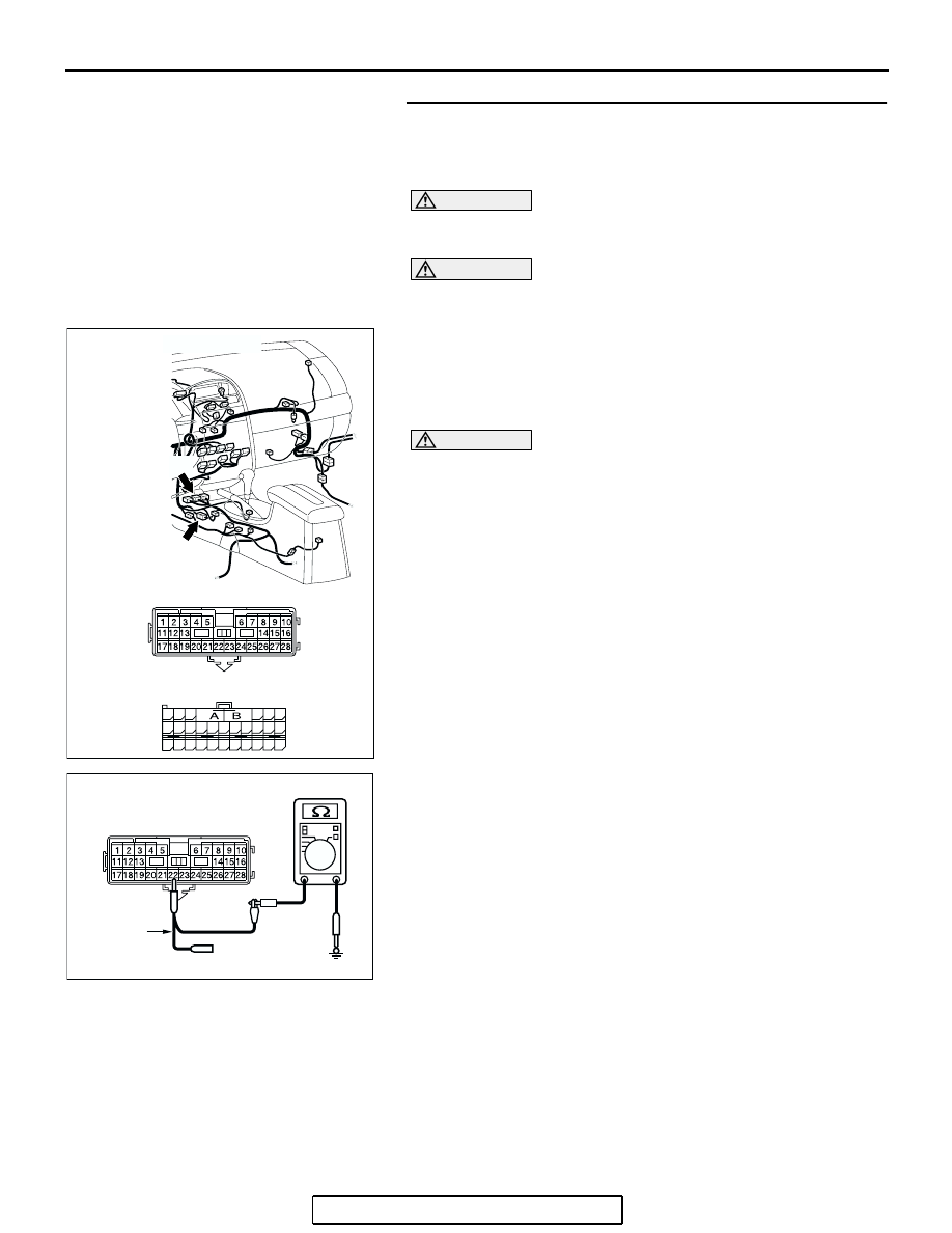
STEP 19. Check the CAN_ H line (communication line only)
between the SRS-ECU connector and the intermediate
connector for a short circuit. Measure the resistance at
intermediate connector C-22.
CAUTION
A digital multimeter should be used. For details refer to
.
CAUTION
The test wiring harness should be used. For details refer to
.
(1) Disconnect intermediate connector C-22 and SRS-ECU
connector C-121, and measure the resistance at the male
side of intermediate connector C-22 (at floor wiring harness
side).
(2) Turn the ignition switch to the "LOCK" (OFF) position.
CAUTION
Disconnect the negative battery terminal. For details refer
to
(3) Disconnect the negative battery terminal.
(4) Measure the resistance between intermediate connector
terminal 22 and body ground.
OK: 1 k
Ω or more
Q: Does the resistance measure 1 k
Ω or more?
YES : If the resistance measures 1 k
Ω or more, diagnose
CAN bus lines thoroughly by referring to
NO : If the resistance measures less than 1 k
Ω, repair the
wiring harness between intermediate connector C-29
and SRS-ECU connector.
AC305234AC
CONNECTORS: C-22, C-121
C-121 HARNESS SIDE
C-121 (Y)
C-22 (Y)
C-22
48
21
22
23
24
25
26
27
28
29
30
31
32
33
34
35
36
37
38
39
40
41
42
43
44
45
46
47
AC209364IA
MAIL SIDE: C-22
TEST
HARNESS