Mitsubishi Galant 9G. Manual - part 1249


  Index      Mitsubishi     Mitsubishi Galant 9G - service repair manual


Search            


Content   ..  1247  1248  1249  1250   ..


Mitsubishi Galant 9G. Manual - part 1249


DIAGNOSIS

TSB Revision

CONTROLLER AREA NETWORK (CAN)

54C-100

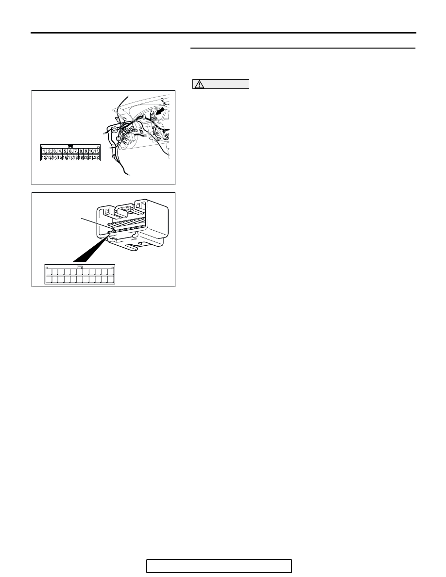
STEP 29. Check joint connector (3) C-02 for loose, 
corroded or damaged terminals, or terminals pushed back 
in the connector.

CAUTION

The strand end of the twisted wire should be within 10 cm 
(4 inches) from the connector. For details refer to 

P.54C-4

.

Check the joint connector at the wiring harness side for loose, 
corroded or damaged terminals, or terminals pushed back in 
the connector, and also check the short pin behind the connec-
tor for corrosion, deformation and delamination.
Q: Is joint connector (3) C-02  in good condition?

YES : Go to Step 30.
NO :  Repair the damaged parts. Replace the joint 

connector as necessary.

AC305231AP

CONNECTOR: C-02

AC209350

1

12

2

13

3

14

4

15

5

16

6

17

7

18

8

19

9

20

10

21

11

22

AB

SHORT PIN

DIAGNOSIS

TSB Revision

CONTROLLER AREA NETWORK (CAN)

54C-101

STEP 30. Check the CAN_L line (communication line 
including the combination meter) between joint connector 
(3) and the combination meter connector for a short to the 
power supply. Measure the voltage at joint connector (3) 
C-02.

CAUTION

A digital multimeter should be used. For details refer to 

P.54C-4

.

CAUTION

The test wiring harness should be used. For details refer to 

P.54C-4

.

(1) Disconnect joint connector (3) C-02, and measure the 

voltage at the wiring harness side of joint connector (3) 
C-02.

(2) Turn the ignition switch to the "ON" position.

(3) Measure the voltage between joint connector (3) terminal 

15 and body ground.

OK: 4.0 V or less

Q: Does the voltage measure 4.0 V or less?

YES : If the voltage measures 4.0 V or less, go to Step 32.
NO :  If the voltage measures more than 4.0 V, go to Step 

31.

AC305231AP

CONNECTOR: C-02

AC209365

11

22

10

21

9

20

8

19

7

18

6

17

5

16

4

15

3

14

2

13

1

12

AC209365

AC209365GB

HARNESS SIDE: C-02

TEST 
HARNESS

DIAGNOSIS

TSB Revision

CONTROLLER AREA NETWORK (CAN)

54C-102

STEP 31. Check the CAN_L line (communication line only) 
between joint connector (3) and the combination meter 
connector  for a short to the power supply. Measure the 
voltage at joint connector (3) C-02.

CAUTION

A digital multimeter should be used. For details refer to 

P.54C-4

.

CAUTION

The test wiring harness should be used. For details refer to 

P.54C-4

.

(1) Disconnect joint connector (3) C-02 and combination meter 

connector C-101, and measure the voltage at the wiring 
harness side of joint connector (3) C-02.

(2) Turn the ignition switch to the "ON" position.

(3) Measure the voltage between joint connector (3) terminal 

15 and body ground.

OK: 1.0 V or less

CAUTION

Strictly observe the specified wiring harness repair proce-
dure. For details refer to 

P.54C-5

.

Q: Does the voltage measure 1.0 V or less?

YES : If the voltage measures 1.0 V or less, diagnose CAN 

bus lines thoroughly by referring to 

P.54C-486

.

NO :  If the voltage measures more than 1.0 V, repair the 

wiring harness between joint connector (3) and the 
combination meter connector.

AC305232

HARNESS SIDE

C-101

CONNECTORS: C-02, C-101

AE

C-02

C-02

C-101

AC209365

11

22

10

21

9

20

8

19

7

18

6

17

5

16

4

15

3

14

2

13

1

12

AC209365

AC209365GB

HARNESS SIDE: C-02

TEST 
HARNESS

DIAGNOSIS

TSB Revision

CONTROLLER AREA NETWORK (CAN)

54C-103

STEP 32. Check the CAN_L line (communication line 
including the ETACS-ECU) between joint connector (3) and 
the ETACS-ECU connector for a short to the power supply. 
Measure the voltage at joint connector (3) C-02.

CAUTION

A digital multimeter should be used. For details refer to 

P.54C-4

.

CAUTION

The test wiring harness should be used. For details refer to 

P.54C-4

.

(1) Disconnect joint connector (3) C-02, and measure the 

voltage at the wiring harness side of joint connector (3) 
C-02.

(2) Turn the ignition switch to the "ON" position.

(3) Measure the voltage between joint connector (3) terminal 

16 and body ground.

OK: 4.0 V or less

Q: Does the voltage measure 4.0 V or less?

YES : If the voltage measures 4.0 V or less, go to Step 35.
NO :  If the voltage measures more than 4.0 V, go to Step 

33.

STEP 33. Check ETACS-ECU connector C-218 for loose, 
corroded or damaged terminals, or terminals pushed back 
in the connector.

CAUTION

The strand end of the twisted wire should be within 10 cm 
(4 inches) from the connector. For details refer to 

P.54C-4

.

Q: Is ETACS-ECU connector C-218 in good condition?

YES : Go to Step 34.
NO :  Repair the damaged parts.

AC305231AP

CONNECTOR: C-02

AC209365

11

22

10

21

9

20

8

19

7

18

6

17

5

16

4

15

3

14

2

13

1

12

AC209365

AC209365GC

HARNESS SIDE: C-02

TEST 
HARNESS

AC305413

C-218 (GR)

CONNECTOR: C-218

AI

HARNESS SIDE

JUNCTION BLOCK
(REAR VIEW)

68

74

63

66

72

73

67

65 64

61

70

71

62

69

60

57

58

59

56 55

52

54 53

51


Content   ..  1247  1248  1249  1250   ..