Mitsubishi Galant 9G. Manual - part 1248


  Index      Mitsubishi     Mitsubishi Galant 9G - service repair manual


Search            


Content   ..  1246  1247  1248  1249   ..


Mitsubishi Galant 9G. Manual - part 1248


DIAGNOSIS

TSB Revision

CONTROLLER AREA NETWORK (CAN)

54C-96

STEP 25. Check the CAN_H line (communication line only) 

between the powertrain control module  connector and 

ABS-ECU connector for a short to the power supply. 

Measure voltage at powertrain control module connector 

B-19.

CAUTION

A digital multimeter should be used. For details refer to 

P.54C-4

.

CAUTION

The test wiring harness should be used. For details refer to 

P.54C-4

.

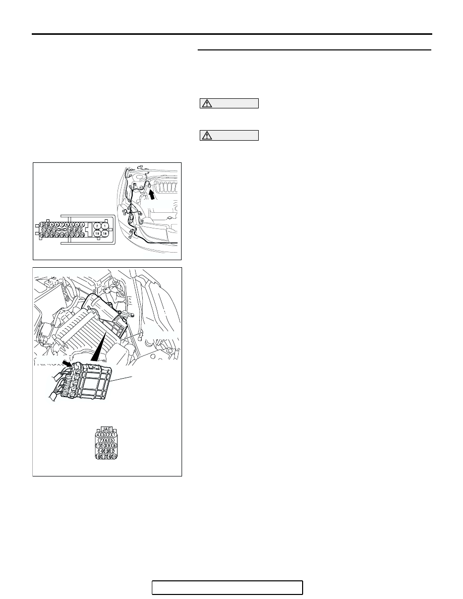
(1) Disconnect powertrain control module connector B-19 and 

ABS-ECU connector A-02, and measure the voltage at the 
harness side of powertrain control module connector B-19.

(2) Turn the ignition switch to the "ON" position.

AC305206

CONNECTOR: A-02

AG

A-02 (GR)

HARNESS SIDE

AC306248AD

B-19 (B)

CONNECTOR: B-19

PCM

AIR
CLEANER

HARNESS SIDE

DIAGNOSIS

TSB Revision

CONTROLLER AREA NETWORK (CAN)

54C-97

(3) Measure the voltage between powertrain control module 

connector terminal 17 and body ground.

OK: 1.0 V or less

CAUTION

Strictly observe the specified wiring harness repair proce-
dure. For details refer to 

P.54C-5

.

Q: Does the voltage measure 1.0 V or less?

YES : If the voltage measures 1.0 V or less, go to Step 26.
NO :  If the voltage measures more than 1.0 V, repair the 

wiring harness between powertrain control module 
connector and ABS-ECU connector.

STEP 26. Check the CAN_H line inside the ABS-ECU for a 
short to the power supply. Measure the voltage at 
ABS-ECU connector A-02.

CAUTION

A digital multimeter should be used. For details refer to 

P.54C-4

.

CAUTION

The test wiring harness should be used. For details refer to 

P.54C-4

.

(1) Disconnect ABS-ECU connector A-02.

AC209365

AC209365

AC209365FZ

HARNESS SIDE: B-19

TEST 
HARNESS

AC305206

CONNECTOR: A-02

AG

A-02 (GR)

HARNESS SIDE

DIAGNOSIS

TSB Revision

CONTROLLER AREA NETWORK (CAN)

54C-98

(2) Connect special tool MB991970 (ABS check harness) to 

the ABS-ECU and the wiring harness, and measure the 
voltage at special tool MB991970 (ABS check harness).

(3) Turn the ignition switch to the "ON" position.
(4) Measure the voltage between special tool MB991970 (ABS 

check harness) connector terminal 25 and body ground.

OK: 4.0 V or less

Q: Does the voltage measure 4.0 V or less?

YES : If the voltage measures 4.0 V or less, diagnose CAN 

bus lines thoroughly by referring to 

P.54C-486

.

NO :  If the voltage measures more than 4.0 V, replace the 

ABS-ECU.

STEP 27. Check intermediate connector C-29 for loose, 
corroded or damaged terminals, or terminals pushed back 
in the connector.

CAUTION

The strand end of the twisted wire should be within 10 cm 
(4 inches) from the connector. For details refer to 

P.54C-4

.

Q: Is intermediate connector C-29 in good condition?

YES : Go to Step 28.
NO :  Repair the damaged parts.

AC209767

2

19

1

18

25

8

15

16

17

27

28

26

11

9

10

12

13

14

23

24

22 21

7

6

5

4

20

3

TEST 
HARNESS

SPECIAL TOOL
MB991970

ABS-
ECU

MEASURE AT THIS CONNECTOR

SPECIAL TOOL MB991970 
CONNECTOR

AC

AC305231AI

CONNECTOR: C-29

DIAGNOSIS

TSB Revision

CONTROLLER AREA NETWORK (CAN)

54C-99

STEP 28. Check the CAN_L-side bus line (communication 
line including) of the front wiring harness for a short to the 
power supply. Measure the voltage at intermediate 
connector C-29.

CAUTION

A digital multimeter should be used. For details refer to 

P.54C-4

.

CAUTION

The test wiring harness should be used. For details refer to 

P.54C-4

.

(1) Disconnect intermediate connector C-29, and measure the 

voltage at the male side (at front wiring harness side).

(2) Turn the ignition switch to the "ON" position.

(3) Measure the voltage between intermediate connector 

terminal 12 and body ground.

OK: 4.0 V or less

Q: Does the voltage measure 4.0 V or less?

YES : If the voltage measures 4.0 V or less, go to Step 29.
NO :  If the voltage measures more than 4.0 V, go to Step 

46.

AC305231AI

CONNECTOR: C-29

AC209365

2 3

27

32

28

33

16

15

4 5

19

18

29

17

34

7 8

35

22

21

9 10

30

36

31

37

25

24

23

6

20

1

14

26

11

13

12

38

AC209365

MALE SIDE: C-29

TEST HARNESS

GA


Content   ..  1246  1247  1248  1249   ..