Mitsubishi Galant 9G. Manual - part 124


  Index      Mitsubishi     Mitsubishi Galant 9G - service repair manual


Search            


Content   ..  122  123  124  125   ..


Mitsubishi Galant 9G. Manual - part 124


INPUT SIGNAL PROCEDURES

TSB Revision

SIMPLIFIED WIRING SYSTEM (SWS)

54B-492

DIAGNOSIS

Required Special Tool:

• MB991223: Harness Set

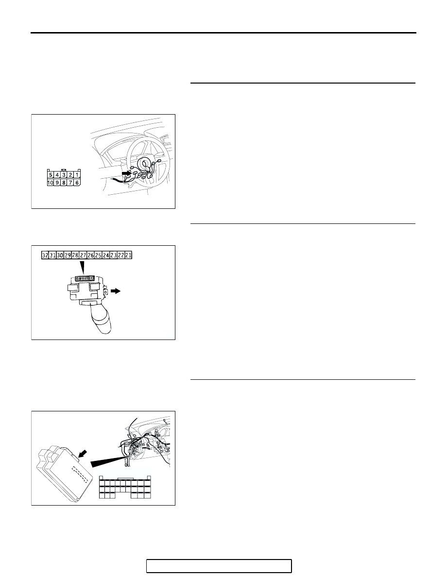
STEP 1. Check column switch connector C-309 for loose, 
corroded or damaged terminals, or terminals pushed back 
in the connector.
Q: Is column switch connector C-309 in good condition?

YES : Go to Step 2.
NO :  Repair or replace the damaged component(s). Refer 

to GROUP 00E, Harness Connector Inspection 

P.00E-2

. If the wiper interval can be adjusted 

normally, the variable intermittent wiper control switch 
should send a signal to the ECU.

STEP 2. Check the variable intermittent wiper control 
switch.
(1) Remove the windshield wiper and washer switch, and 

check at the switch side.

(2) Measure the resistance value between terminals 27 and 28. 

The measured resistance should change smoothly from 
approximately 0 ohm ("FAST" position) to 1 k

Ω ("SLOW" 

position).

Q: Is the variable intermittent wiper control switch in good 

condition?
YES : 
Go to Step 3.
NO :  Replace the column switch (windshield wiper and 

washer switch). If the wiper interval can be adjusted 
normally, that the variable intermittent wiper control 
switch should send a signal to the ECU.

STEP 3. Check ETACS-ECU connector C-218 for loose, 
corroded or damaged terminals, or terminals pushed back 
in the connector.
Q: Is ETACS-ECU connector C-218 in good condition?

YES : Go to Step 4.
NO :  Repair or replace the damaged component(s). Refer 

to GROUP 00E, Harness Connector Inspection 

P.00E-2

. If the wiper interval can be adjusted 

normally, that the variable intermittent wiper control 
switch should send a signal to the ECU.

AC305235

HARNESS SIDE

CONNECTOR: C-309

AE

AC003178

UPPER SIDE

AB

AC305413AN

CONNECTOR: C-218

JUNCTION BLOCK
(REAR VIEW)

C-218 (GR)

HARNESS SIDE

51

52

53

54

55

56

57

58

59

60

61

62

63

64

65

66

67

68

69

70

71

72

73

74

INPUT SIGNAL PROCEDURES

TSB Revision

SIMPLIFIED WIRING SYSTEM (SWS)

54B-493

STEP 4. Check the wiring harness between column switch 
connector C-309 (terminal 6) and ETACS-ECU connector 
C-218 (terminal 66).
Q: Is the wiring harness between column switch connector 

C-309 (terminal 6) and ETACS-ECU connector C-218 
(terminal 66) in good condition?
YES : 
Go to Step 5.
NO :  The wiring harness may be damaged or the 

connector(s) may have loose, corroded or damaged 
terminals, or terminals pushed back in the connector. 
Repair the wiring harness as necessary. If the wiper 
interval can be adjusted normally, the variable 
intermittent wiper control switch should send a signal 
to the ECU.

STEP 5. Replace the column switch.
(1) Replace the column switch.
(2) If the wiper interval can be adjusted normally, the variable 

intermittent wiper control switch should send a signal to the 
ECU.

Q: Can input signal be confirmed when the variable 

intermittent wiper control switch is operated?
YES : 
No action is necessary and testing is complete.
NO :  Replace the ETACS-ECU. If the wiper interval can be 

adjusted normally, the variable intermittent wiper 
control switch should send a signal to the ECU.

AC305413AN

CONNECTOR: C-218

JUNCTION BLOCK
(REAR VIEW)

C-218 (GR)

HARNESS SIDE

51

52

53

54

55

56

57

58

59

60

61

62

63

64

65

66

67

68

69

70

71

72

73

74

AC305235

HARNESS SIDE

CONNECTOR: C-309

AE

INPUT SIGNAL PROCEDURES

TSB Revision

SIMPLIFIED WIRING SYSTEM (SWS)

54B-494

INSPECTION PROCEDURE M-8: Sunroof Switch: ETACS-ECU does not receive any signal from the 
up, open or close/down switch.

SUNROOF MOTOR 
ASSEMBLY

OVERHEAD 
CONSOLE 
ASSEMBLY

SUNROOF-ECU

SUNROOF 
SWITCH

JOINT 
CONNECTOR (3)

ETACS-
ECU

Sunroof Switch Input Circuit

AC305231

AC305231BV

CONNECTORS: C-03, C-27

C-03

C-27

AC305413AL

CONNECTOR: C-218

C-218 (GR)

AC400530

AI

CONNECTOR: D-04

HARNESS SIDE

INPUT SIGNAL PROCEDURES

TSB Revision

SIMPLIFIED WIRING SYSTEM (SWS)

54B-495

.

CIRCUIT OPERATION

The ETACS-ECU receives a signal through the sun-
roof motor assembly via the SWS communication 
line from the sunroof switch, and sends a signal to 
the data link connector.

.

TECHNICAL DESCRIPTION (COMMENT)

If the SWS communication line between the sunroof 
motor assembly and the ETACS-ECU is defective, 
the ETACS-ECU cannot identify the input signal from 
the sunroof switch even if the sunroof is normal.

.

TROUBLESHOOTING HINTS

• The wiring harness or connectors may have 

loose, corroded, or damaged terminals, or termi-
nals pushed back in the connector

• The sunroof motor assembly may be defective

• The ETACS-ECU may be defective

DIAGNOSIS

Required Special Tool:

• MB991223: Test Harness Set

STEP 1. Check the sunroof operation.
Q: Does the sunroof work normally?

YES : Go to Step 2.
NO :  Refer to Inspection Procedure F-1 "Sunroof does not 

operate 

P.54B-239

."

STEP 2. Check sunroof motor assembly connector D-04 
and ETACS-ECU connector C-218 for loose, corroded or 
damaged terminals, or terminals pushed back in the 
connector.
Q: Are sunroof motor assembly connector D-04 and 

ETACS-ECU connector C-218 in good condition?
YES : 
Go to Step 3.
NO :  Repair or replace the damaged component(s). Refer 

to GROUP 00E, Harness Connector Inspection 

P.00E-2

. If the sunroof operates normally, a correct 

signal is sent from the sunroof switch.

AC305413AN

CONNECTOR: C-218

JUNCTION BLOCK
(REAR VIEW)

C-218 (GR)

HARNESS SIDE

51

52

53

54

55

56

57

58

59

60

61

62

63

64

65

66

67

68

69

70

71

72

73

74

AC400530

AI

CONNECTOR: D-04

HARNESS SIDE


Content   ..  122  123  124  125   ..