Mitsubishi Galant 9G. Manual - part 1227


  Index      Mitsubishi     Mitsubishi Galant 9G - service repair manual


Search            


Content   ..  1225  1226  1227  1228   ..


Mitsubishi Galant 9G. Manual - part 1227


DIAGNOSTIC TROUBLE CODE DIAGNOSIS

TSB Revision

CONTROLLER AREA NETWORK (CAN)

54C-12

DIAGNOSTIC TROUBLE CODE DIAGNOSIS

M1548304500025

ON-BOARD DIAGNOSTICS

The CAN is a communication method which the 
ECUs use in order to communicate each other. The 
CAN-related diagnostic trouble codes will be stored 
in the following ECUs, which use the CAN communi-
cation.

• Powertrain control module

• ABS-ECU

• ETACS-ECU

• A/C-ECU

• SRS-ECU

• Combination meter

• Multi-center display (middle-grade type)

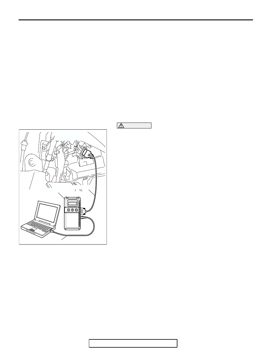
HOW TO CONNECT THE SCAN TOOL (MUT-III)

Required Special Tools:

•  MB991958: Scan Tool (MUT-III Sub Assembly)

• MB991824: Vehicle Communication Interface (V.C.I.)

• MB991827: MUT-III USB Cable

• MB991910: MUT-III Main Harness A

CAUTION

To prevent damage to scan tool MB991958, always turn the 
ignition switch to the "LOCK" (OFF) position before con-
necting or disconnecting scan tool MB991958.
1. Ensure that the ignition switch is at the "LOCK" (OFF) 

position.

2. Start up the personal computer.
3. Connect special tool MB991827 to special tool MB991824 

and the personal computer.

4. Connect special tool MB991910 to special tool MB991824.
5. Connect special tool MB991910 to the data link connector.
6. Turn the power switch of special tool MB991824 to the "ON" 

position.
NOTE: When special tool MB991824 is energized, special 
tool MB991824 indicator light will be illuminated in a green 
color.

7. Start the MUT-III system on the personal computer.
NOTE: Disconnecting scan tool MB991958 is the reverse of the 
connecting sequence, making sure that the ignition switch is at 
the "LOCK" (OFF) position.

HOW TO DIAGNOSE THE CAN BUS LINE

Required Special Tools:

•  MB991958: Scan Tool (MUT-III Sub Assembly)

• MB991824: Vehicle Communication Interface (V.C.I.)

• MB991827: MUT-III USB Cable

• MB991910: MUT-III Main Harness A

AC206894

AB

MB991910

DATA LINK

CONNECTOR

MB991824

MB991827

DIAGNOSTIC TROUBLE CODE DIAGNOSIS

TSB Revision

CONTROLLER AREA NETWORK (CAN)

54C-13

CAUTION

To prevent damage to scan tool MB991958, always turn the 
ignition switch to the "LOCK" (OFF) position before con-
necting or disconnecting scan tool MB991958.
1. Connect scan tool MB991958 to the data link connector.
2. Turn the ignition switch to the "ON" position.
3. Select "CAN bus diagnosis" from the start-up screen.
4. When the vehicle information is displayed, confirm that it 

matches the vehicle whose CAN bus lines will be 
diagnosed.

• If they match, go to step 8.

• If not, go to step 5.

5. Select the "view vehicle information" button.
6. Enter the vehicle information and select the "OK" button.
7. When the vehicle information is displayed, confirm again 

that it matches the vehicle whose CAN bus lines will be 
diagnosed.

• If they match, go to step 8.

• If not, go to step 5.

8. Select the "OK" button.
9. When the optional equipment screen is displayed, choose 

the one which the vehicle is fitted with, and then select the 
"OK" button.

AC206894

AB

MB991910

DATA LINK

CONNECTOR

MB991824

MB991827

DIAGNOSIS

TSB Revision

CONTROLLER AREA NETWORK (CAN)

54C-14

DIAGNOSIS

CAN BUS DIAGNOSTICS TABLE

M1548300200055

This diagnosis applies only to the CAN bus lines. If a 
different system is defective, proceed to the applica-
ble diagnosis section for each system. Observe the 
diagnosis procedure below only when the CAN bus 
line is defective.

CAUTION

During diagnosis, a DTC code associated with 
another system may be set when the ignition 
switch is turned on with connector(s) discon-
nected. After completing the repair, confirm all 
systems for DTC code(s). If DTC code(s) are set, 
erase them all.

Vehicles without ABS and vehicles without multi-center display (middle-grade type)

MUT-III SCREEN

DIAGNOSIS DETAILS

REFERENCE 
PAGE

<Comment>
Short circuit to battery in red displayed area is 
estimated.

Diagnostic Item 1
Diagnose shorts in the power supply to 
CAN bus line <Vehicles without ABS 
and vehicles without multi-center display 
(middle-grade type)>

P.54C-31

<Comment>
Grounding in red displayed area is 
estimated.

Diagnostic Item 4
Diagnose shorts in the ground to CAN 
bus line <Vehicles without ABS and 
vehicles without multi-center display 
(middle-grade type)>

P.54C-167

<Comment>
Short circuit between CAN_H and CAN_L in red 
displayed area is 
estimated.

Diagnostic Item 7
Diagnose shorts between CAN_L and H 
lines <Vehicles without ABS and 
vehicles without multi-center display 
(middle-grade type)>

P.54C-304

AC305790

ETACS

-ECU

AC-ECU

: Red section on screen

PCM

SRS-ECU

METER

-ECU

AB

MUT

J/C

AC305790

ETACS

-ECU

AC-ECU

: Red section on screen

PCM

SRS-ECU

METER

-ECU

AB

MUT

J/C

AC305790

ETACS

-ECU

AC-ECU

: Red section on screen

PCM

SRS-ECU

METER

-ECU

AB

MUT

J/C

DIAGNOSIS

TSB Revision

CONTROLLER AREA NETWORK (CAN)

54C-15

<Comment>
Disconnection in red displayed area is 
estimated.

Diagnostic Item 10
Diagnose terminator resistors at both 
ends <Vehicles without ABS>

P.54C-390

MUT-III SCREEN

DIAGNOSIS DETAILS

REFERENCE 
PAGE

AC305790

: Red section on screen

PCM

METER

-ECU

AC

MUT

ETACS

-ECU

AC-ECU

SRS-ECU

J/C


Content   ..  1225  1226  1227  1228   ..