Mitsubishi Galant 9G. Manual - part 115
SYMPTOM PROCEDURES
TSB Revision
SIMPLIFIED WIRING SYSTEM (SWS)
54B-456
INSPECTION PROCEDURE K-6: Interior Light: The door ajar indicator lights do not illuminate or go
out normally
NOTE: This troubleshooting procedure requires the
use of scan tool MB991958 and SWS monitor kit
MB991813. For details on how to use the SWS mon-
itor, refer to "How to use SWS monitor
.
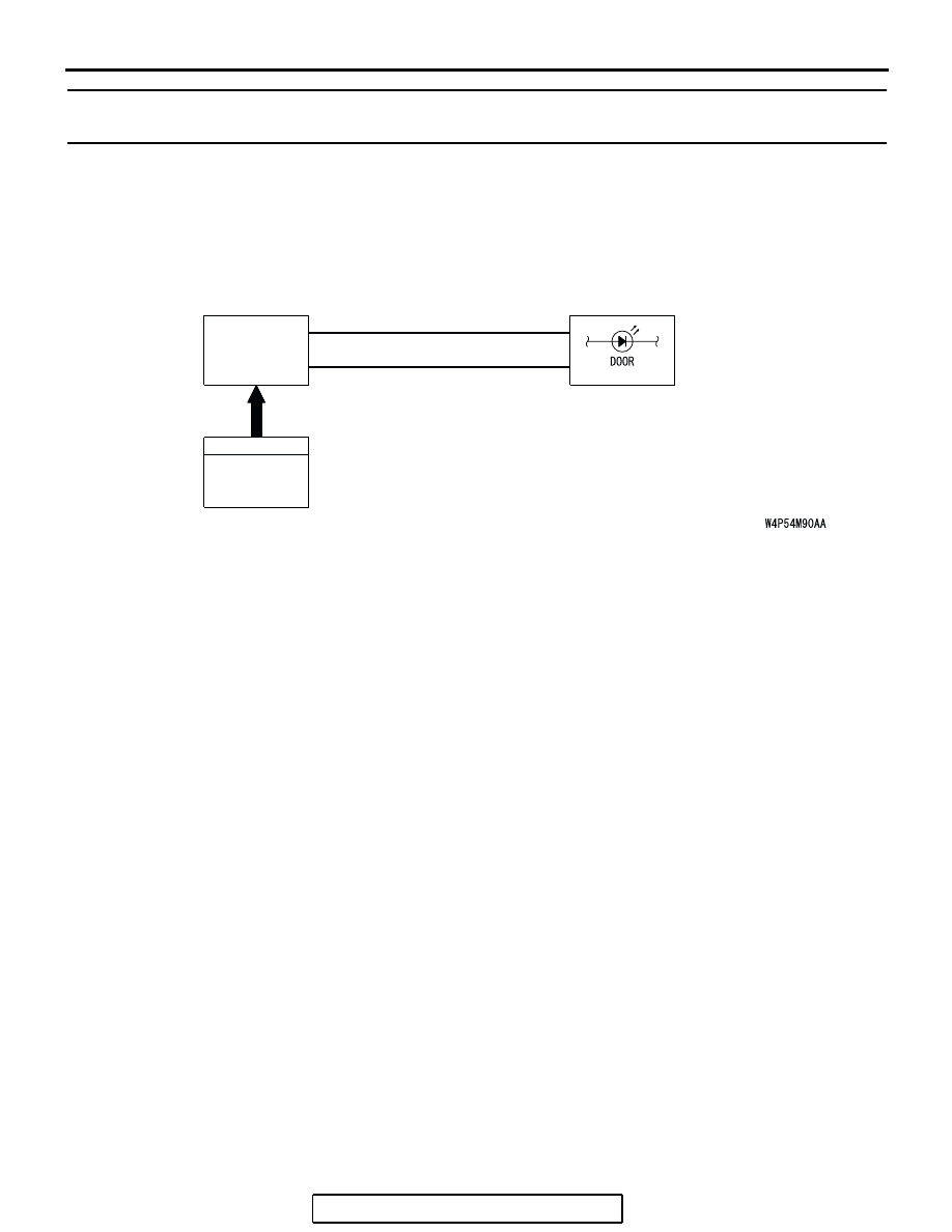
CIRCUIT OPERATION
The combination meter receives the door switches
signals from the ETACS-ECU, and then controls the
door ajar indicator, based on these signals.
.
TECHNICAL DESCRIPTION (COMMENT)
If the door ajar indicator does not illuminate, connec-
tor(s), wiring harness in the CAN bus lines, the door
switches, the ETACS-ECU, or the combination meter
may be defective.
.
TROUBLESHOOTING HINTS
• Trouble in input signal system
• The wiring harness or connectors may have
loose, corroded, or damaged terminals, or termi-
nals pushed back in the connector
• The combination meter may be defective
• The ETACS-ECU may be defective
DIAGNOSIS
Required Special Tools:
• MB991223: Harness Set
• MB991958: Scan Tool (MUT-III Sub Assembly)
• MB991824: Vehicle Communication Interface (V.C.I.)
• MB991827: MUT-III USB Cable
• MB991910: MUT-III Main Harness A
• MB991813: SWS Monitor Kit
• MB991806: SWS Monitor Cartridge
• MB991812: SWS Monitor Harness (For Column-ECU)
• MB991822: Probe Harness
ALL DOOR
SWITCHES
INPUT SIGNAL
ETACS-
ECU
COMBINATION
METER
CAN COMMUNICATION LINE
(CAN_L LINE)
CAN COMMUNICATION LINE
(CAN_H LINE)
Door Ajar Indicator Light Circuit