Mitsubishi Galant 9G. Manual - part 112
SYMPTOM PROCEDURES
TSB Revision
SIMPLIFIED WIRING SYSTEM (SWS)
54B-444
.
CIRCUIT OPERATION
• When the driver's door is opened with the ignition
switch at "ACC" position, the ETACS-ECU illumi-
nates the ignition key hole illumination light.
• The ignition key hole illumination light goes out in
30 seconds after the driver's door is closed. The
ignition key hole illumination light remains illumi-
nated for 30 seconds after the ignition key is
pulled out.
• The ETACS-ECU operates the ignition key hole
illumination light according to the input signals
from the following switches:
• Ignition switch (IG1): OFF
• Key reminder switch: OFF
• Interior light loaded signal: ON
• Vehicle condition:
• Ignition switch: "LOCK" (OFF) or "ACC" posi-
tion
• Ignition key: Removed from the ignition key
cylinder
• Driver’s door: Opened or closed
.
TECHNICAL DESCRIPTION (COMMENT)
If the ignition key hole illumination light does not illu-
minate, the input circuits from the switches described
in "CIRCUIT OPERATION", the key reminder switch
(ignition key hole illumination light bulb) or the
ETACS-ECU may be defective.
.
TROUBLESHOOTING HINTS
• Trouble in input signal system
• The wiring harness or connectors may have
loose, corroded, or damaged terminals, or termi-
nals pushed back in the connector
• The ETACS-ECU may be defective
DIAGNOSIS
Required Special Tools:
• MB991223: Harness Set
• MB991958: Scan Tool (MUT-III Sub Assembly)
• MB991824: Vehicle Communication Interface (V.C.I.)
• MB991827: MUT-III USB Cable
• MB991910: MUT-III Main Harness A
• MB991813: SWS Monitor Kit
• MB991806: SWS Monitor Cartridge
• MB991812: SWS Monitor Harness (For Column-ECU)
• MB991822: Probe Harness
AC305235
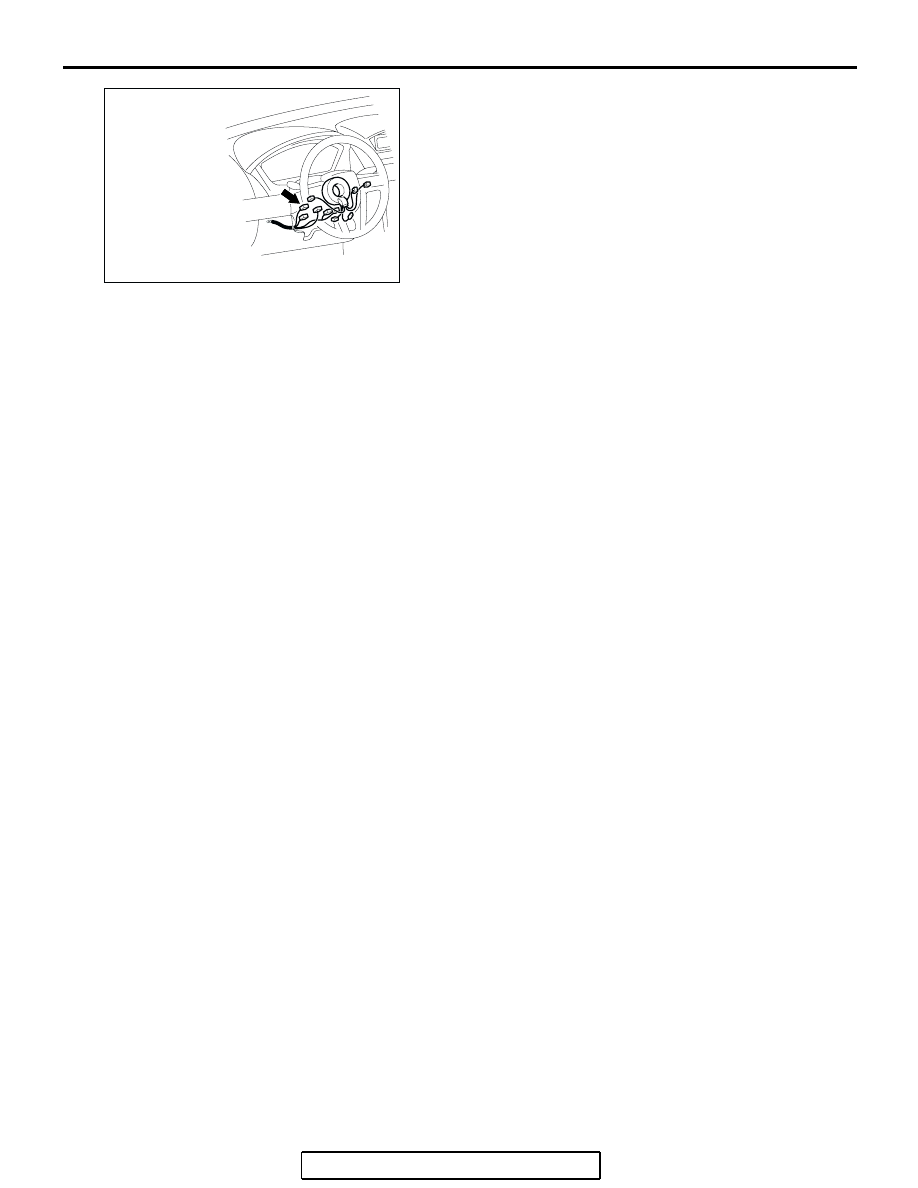
CONNECTOR: C-310
AD