Mitsubishi Galant 9G. Manual - part 110


  Index      Mitsubishi     Mitsubishi Galant 9G - service repair manual


Search            


Content   ..  108  109  110  111   ..


Mitsubishi Galant 9G. Manual - part 110


SYMPTOM PROCEDURES

TSB Revision

SIMPLIFIED WIRING SYSTEM (SWS)

54B-436

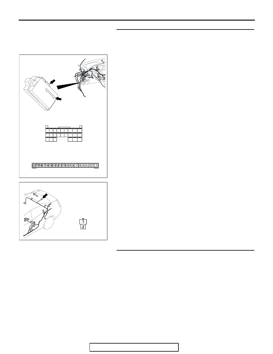
STEP 15. Check trunk light connector D-10, ETACS-ECU 
connectors C-218 and C-219 for loose, corroded or 
damaged terminals, or terminals pushed back in the 
connector.
Q: Is trunk light connector D-10, ETACS-ECU connectors 

C-218 and C-219 in good condition?
YES : 
Go to Step 16.
NO :  Repair or replace the damaged component(s). Refer 

to GROUP 00E, Harness Connector Inspection 

P.00E-2

. Check that the trunk light illuminates 

normally.

STEP 16. Check the trunk light bulb.
Q: Is the trunk light bulb in good condition?

YES : Go to Step 17.
NO :  Replace the trunk light bulb. Check that the trunk light 

illuminates normally.

AC305414

CONNECTORS: C-218, C-219

JUNCTION BLOCK
(REAR VIEW)

C-219

C-218 (GR)

HARNESS SIDE

C-218

C-219

51

52

53

54

55

56

57

58

59

60

61

62

63

64

65

66

67

68

69

70

71

72

73

74

JUNCTION BLOCK SIDE

AC

AC400532

HARNESS SIDE

CONNECTOR: D-10

AF

SYMPTOM PROCEDURES

TSB Revision

SIMPLIFIED WIRING SYSTEM (SWS)

54B-437

STEP 17. Check the wiring harness between trunk light 
connector D-10 (terminals 1 and 2) and ETACS-ECU 
connector C-219 (terminal 6) or C-218 (terminal 52).

AC305414

CONNECTORS: C-218, C-219

JUNCTION BLOCK
(REAR VIEW)

C-219

C-218 (GR)

HARNESS SIDE

C-218

C-219

51

52

53

54

55

56

57

58

59

60

61

62

63

64

65

66

67

68

69

70

71

72

73

74

JUNCTION BLOCK SIDE

AC

AC400532

HARNESS SIDE

CONNECTOR: D-10

AF

SYMPTOM PROCEDURES

TSB Revision

SIMPLIFIED WIRING SYSTEM (SWS)

54B-438

NOTE: Also check intermediate connector C-28 and junction 
block connector C-204 for loose, corroded, or damaged termi-
nals, or terminals pushed back in the connector. If intermediate 
connector C-28 or junction block connector C-204 is damaged, 
repair or replace the damaged component(s) as described in 
GROUP 00E, Harness Connector Inspection 

P.00E-2

.

Q: Is the wiring harness between trunk light connector 

D-10 (terminals 1 and 2) and ETACS-ECU connector 
C-219 (terminal 6) or C-218 (terminal 52) in good 
condition?
YES : 
Replace the trunk light. Check that the trunk light 

illuminates normally.

NO :  The wiring harness may be damaged or the 

connector(s) may have loose, corroded or damaged 
terminals, or terminals pushed back in the connector. 
Repair the wiring harness as necessary. Check that 
the trunk light illuminates normally.

INSPECTION PROCEDURE K-3: Interior light: Dome  light dimming function does not work  normally.

NOTE: This troubleshooting procedure requires the 
use of scan tool MB991958 and SWS monitor kit 
MB991813. For details on how to use the SWS mon-
itor, refer to "How to use SWS monitor 

P.54B-15

."

.

AC305231AE

CONNECTOR:C-28

AC305415AJ

CONNECTOR: C-204

HARNESS SIDE

JUNCTION BLOCK

(FRONT VIEW)

ETACS-
ECU

· 

ALL DOOR 

SWITCH

· 

FRONT 

DOOR SWITCH

· IGNITION SWITCH (IG1)
· 

INTERIOR LIGHT 

  LOADED SIGNAL
· KEY REMINDER SWITCH

JUNCTION BLOCK SIDE

JUNCTION 
BLOCK

INPUT SIGNAL

NOTE

WITHOUT SUNROOF
WITH SUNROOF

· 

MAP LIGHT ASSEMBLY

· OVERHEAD CONSOLE 

 ASSEMBLY

· 

REAR DOME LIGHT

· 

TRUNK LIGHT

Ignition Dimming Function

SYMPTOM PROCEDURES

TSB Revision

SIMPLIFIED WIRING SYSTEM (SWS)

54B-439

CIRCUIT OPERATION

The ETACS-ECU operates the dome light dimming 
function according to the input signals from the fol-
lowing switches:

• Ignition switch (IG1): OFF

• Key reminder switch: ON

• Door switches: OFF

• Driver's door lock actuator switch: LOCK or 

UNLOCK

.

TECHNICAL DESCRIPTION (COMMENT)

If the dome lights do not dim normally, the input cir-
cuits from the switches described in "CIRCUIT 
OPERATION" or the ETACS-ECU may be defective.

.

TROUBLESHOOTING HINTS

• Trouble in input signal system

• The wiring harness or connectors may have 

loose, corroded, or damaged terminals, or termi-
nals pushed back in the connector

• The ETACS-ECU may be defective

DIAGNOSIS

Required Special Tools:

• MB991223: Harness Set

• MB991958: Scan Tool (MUT-III Sub Assembly)

• MB991824: Vehicle Communication Interface (V.C.I.)

• MB991827: MUT-III USB Cable

• MB991910: MUT-III Main Harness A

• MB991813: SWS Monitor Kit

• MB991806: SWS Monitor Cartridge

• MB991812: SWS Monitor Harness (For Column-ECU)

• MB991822: Probe Harness

STEP 1. Check the dome light.
If a door is opened while the dome light switch is at 
"door-linked" position, the dome light should illuminate.
Q: Does the dome light illuminate normally?

YES : Go to Step 2.
NO :  Refer to Inspection Procedure K-1 "The dome light do 

not illuminate and go out normally 

P.54B-420

."

STEP 2. Check the adjustment function.
Q: Has the dome light delay-off time been set to other than 

"0 second" by the adjustment function?
YES : 
Go to Step 3.
NO :  Set the dome light delay-off time to "0 second."


Content   ..  108  109  110  111   ..