Mitsubishi Galant 9G. Manual - part 57


  Index      Mitsubishi     Mitsubishi Galant 9G - service repair manual


Search            


Content   ..  55  56  57  58   ..


Mitsubishi Galant 9G. Manual - part 57


SYMPTOM PROCEDURES

TSB Revision

SIMPLIFIED WIRING SYSTEM (SWS)

54B-224

STEP 10. Check the wiring harness between horn relay 
connector A-06X (terminal 4) and horn (HIGH) connector 
A-39 (terminal 1).
Q: Is the wiring harness between horn relay connector 

A-06X (terminal 4) and horn (HIGH) connector A-39 
(terminal 1) in good  condition?
YES : 
Replace the ETACS-ECU. Verify that the horn sounds 

normally.

NO :  The wiring harness may be damaged or the 

connector(s) may have loose, corroded or damaged 
terminals, or terminals pushed back in the connector. 
Repair the wiring harness as necessary. Verify that 
the horn sounds normally.

STEP 11. Check horn connector A-38 (LOW) for loose, 
corroded or damaged terminals, or terminals pushed back 
in the connector.
Q: Is horn (LOW) connector A-38 in good condition?

YES : Go to Step 12.
NO :  Repair or replace the damaged component(s). Refer 

to GROUP 00E, Harness Connector Inspection 

P.00E-2

. Verify that the horn sounds normally.

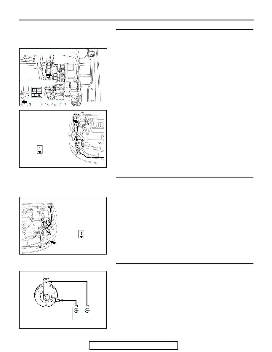
STEP 12. Check the horn (LOW).
Connect the battery as shown, and verify that the horn sounds.
Q: Is the horn normal?

YES : Go to Step 13.
NO :  Replace the horn (LOW). Verify that the horn sounds 

normally.

AC305992

RELAY BOX SIDE

CONNECTOR: A-06X

AC

FRONT OF VEHICLE

AC305206

CONNECTOR: A-39

BE

A-39 (B)

HARNESS SIDE

AC400526

AC

A-38 (B)

CONNECTOR: A-38

HARNESS SIDE

ACX02352

SYMPTOM PROCEDURES

TSB Revision

SIMPLIFIED WIRING SYSTEM (SWS)

54B-225

STEP 13. Check horn relay connector A-06X for loose, 
corroded or damaged terminals, or terminals pushed back 
in the connector.
Q: Is horn relay connector A-06X in good condition?

YES : Go to Step 14.
NO :  Repair or replace the damaged component(s). Refer 

to GROUP 00E, Harness Connector Inspection 

P.00E-2

. Verify that the horn sounds normally.

STEP 14. Check the wiring harness between horn relay 
connector A-06X (terminal 4) and horn (LOW) connector 
A-38 (terminal 1).
Q: Is the wiring harness between horn relay connector 

A-06X (terminal 4) and horn (LOW) connector A-38 
(terminal 1) in good  condition?
YES : 
Replace the ETACS-ECU. Verify that the horn sounds 

normally.

NO :  The wiring harness may be damaged or the 

connector(s) may have loose, corroded or damaged 
terminals, or terminals pushed back in the connector. 
Repair the wiring harness as necessary. Verify that 
the horn sounds normally.

AC305992

RELAY BOX SIDE

CONNECTOR: A-06X

AC

FRONT OF VEHICLE

AC305992

RELAY BOX SIDE

CONNECTOR: A-06X

AC

FRONT OF VEHICLE

AC400526

AC

A-38 (B)

CONNECTOR: A-38

HARNESS SIDE

SYMPTOM PROCEDURES

TSB Revision

SIMPLIFIED WIRING SYSTEM (SWS)

54B-226

STEP 15. Check horn relay connector A-06X for loose, 
corroded or damaged terminals, or terminals pushed back 
in the connector.
Q: Is horn relay connector A-06X in good condition?

YES : Go to Step 16.
NO :  Repair or replace the damaged component(s). Refer 

to GROUP 00E, Harness Connector Inspection 

P.00E-2

. Verify that the horn sounds normally.

STEP 16. Check the horn relay.

Q: Is the horn relay normal?

YES : Go to Step 17.
NO :  Replace the horn relay. Verify that the horn sounds 

normally.

AC305992

RELAY BOX SIDE

CONNECTOR: A-06X

AC

FRONT OF VEHICLE

BATTERY 
VOLTAGE

TESTER 
CONNECTION

SPECIFIED 
CONDITION

Not applied

− 4

Open circuit

• Connect 

terminal 2 to the 
positive battery 
terminal

• Connect 

terminal 3 to the 
negative battery 
terminal

− 4

Less than 2 ohms

AC306638

1

4

3

2

2

1

3

4

FRONT OF 
VEHICLE

HORN RELAY

AB

CONNECTOR: A-06X

SYMPTOM PROCEDURES

TSB Revision

SIMPLIFIED WIRING SYSTEM (SWS)

54B-227

STEP 17. Check the battery power supply circuit to the 
horn relay. Measure the voltage at horn relay connector 
A-06X.
(1) Disconnect horn relay connector A-06X and measure the 

voltage available at the relay box side of the connector.

(2) Measure the voltage between terminal 1 and ground, and 

also between terminal 2 and ground.

• The voltage should measure approximately 12 volts 

(battery positive voltage).

Q: Is the measured voltage approximately 12 volts (battery 

positive voltage)?
YES : 
Go to Step 19.
NO :  Go to Step 18.

STEP 18. Check the wiring harness between horn relay 
connector A-06X (terminals 1 and 2) and the battery.
Q: Is the wiring harness between horn relay connector 

A-06X (terminals 1 and 2) and the battery in good 
condition?
YES : 
No action is necessary and testing is complete.
NO :  The wiring harness may be damaged or the 

connector(s) may have loose, corroded or damaged 
terminals, or terminals pushed back in the connector. 
Repair the wiring harness as necessary. Verify that 
the horn sounds normally.

STEP 19. Check ETACS-ECU connector C-217 for loose, 
corroded or damaged terminals, or terminals pushed back 
in the connector.
Q: Is ETACS-ECU connector C-217 in good condition?

YES : Go to Step 20.
NO :  Repair or replace the damaged component(s). Refer 

to GROUP 00E, Harness Connector Inspection 

P.00E-2

. Verify that the horn sounds normally.

AC305992

RELAY BOX SIDE

CONNECTOR: A-06X

AC

FRONT OF VEHICLE

AC209365EL

CONNECTOR A-06X
(RELAY BOX SIDE)

AC305992

RELAY BOX SIDE

CONNECTOR: A-06X

AC

FRONT OF VEHICLE

AC305413

C-217

CONNECTOR: C-217

AE

HARNESS SIDE

JUNCTION BLOCK

(REAR VIEW)


Content   ..  55  56  57  58   ..