Mitsubishi Galant 9G. Manual - part 53
SYMPTOM PROCEDURES
TSB Revision
SIMPLIFIED WIRING SYSTEM (SWS)
54B-208
NOTE: Also check junction block connector C-215, intermedi-
ate connectors C-28 and D-36. If junction block connector
C-215, intermediate connector C-28 or D-36 is damaged, repair
or replace the connector as described in GROUP 00E, Harness
Connector Inspection
.
Q: Is the wiring harness between power window relay
connector C-203 (terminal 4) and rear power window
sub switch (RH) connector E-06 (terminal 6) in good
condition?
YES : No action is necessary and testing is complete.
NO : The wiring harness may be damaged or the
connector(s) may have loose, corroded or damaged
terminals, or terminals pushed back in the connector.
Repair the wiring harness as necessary. When the
rear power window sub switch (RH) is operated, the
rear power window (RH) should raise and lower
normally.
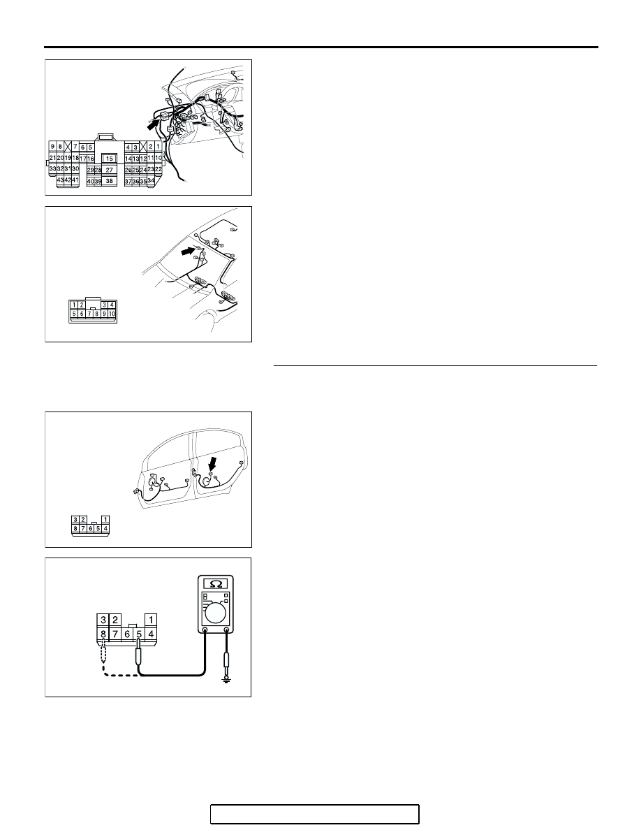
STEP 29. Check the ground circuit to the rear power
window sub switch (RH). Measure the resistance at rear
power window sub switch (RH) connector E-06.
(1) Disconnect rear power window sub switch (RH) connector
E-06 and measure the resistance available at the wiring
harness side of the connector.
(2) Measure the resistance value between terminal 5 and
ground, and also between terminal 8 and ground.
• The resistance should be 2 ohms or less.
Q: Is the measured resistance 2 ohms or less?
YES : Go to Step 31.
NO : Go to Step 30.
AC305231AE
CONNECTOR:C-28
AC400530
AB
CONNECTOR: D-36
AC305333
CONNECTOR:E-06
HARNESS SIDE
AE
AC209364FY
CONNECTOR E-06
(HARNESS SIDE)