Mitsubishi Galant 9G. Manual - part 45


  Index      Mitsubishi     Mitsubishi Galant 9G - service repair manual


Search            


Content   ..  43  44  45  46   ..


Mitsubishi Galant 9G. Manual - part 45


SYMPTOM PROCEDURES

TSB Revision

SIMPLIFIED WIRING SYSTEM (SWS)

54B-176

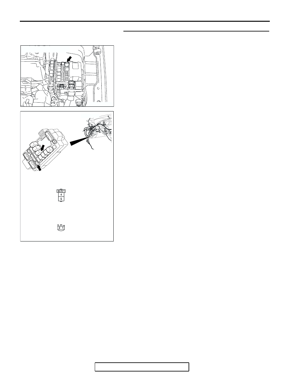
STEP 6. Check the wiring harness between power window 
relay connector C-203 (terminal 5) and fusible link (5).

NOTE: Also check junction block connector C-212 for loose, 
corroded or damaged terminals, or terminals pushed back in 
the connectors. If junction block connector C-212 is damaged, 
repair or replace the damaged component(s) as described in 
GROUP 00E, Harness Connector Inspection 

P.00E-2

.

Q: Is the wiring harness between power window relay 

connector C-203 (terminal 5) and fusible link (5) in good 
condition?
YES : 
No action is necessary and testing is complete.
NO :  The wiring harness may be damaged or the 

connector(s) may have loose, corroded or damaged 
terminals, or terminals pushed back in the connector. 
Repair the wiring harness as necessary. The power 
windows function should now work normally.

AC305015

FUSIBLE LINK No.5

AC

AC305416

C-212

JUNCTION BLOCK SIDE

C-203

C-212

HARNESS SIDE

AB

CONNECTORS: C-203,C-212

C-203

JUNCTION BLOCK

(FRONT VIEW)

SYMPTOM PROCEDURES

TSB Revision

SIMPLIFIED WIRING SYSTEM (SWS)

54B-177

STEP 7. Check the ground circuit to the power window 
relay. Measure the resistance at power window relay 
connector C-203.
(1) Disconnect power window relay connector C-203 and 

measure the resistance available at the junction block side 
of the connector.

(2) Measure the resistance value between terminal 3 and 

ground.

• The resistance should be 2 ohms or less.

Q: Is the measured resistance 2 ohms or less?

YES : Go to Step 9.
NO :  Go to Step 8.

STEP 8. Check the wiring harness between power window 
relay connector C-203 (terminal 3) and ground.

AC305415 AC

JUNCTION BLOCK SIDE

CONNECTOR:C-203

JUNCTION BLOCK

(FRONT VIEW)

AC209364FU

CONNECTOR C-203
(JUNCTION BLOCK SIDE)

AC305416 AC

3

4

5

1

2

JUNCTION BLOCK SIDE

C-203

HARNESS SIDE

C-211

CONNECTORS: C-203,C-211

C-203

C-211

JUNCTION BLOCK

(FRONT VIEW)

SYMPTOM PROCEDURES

TSB Revision

SIMPLIFIED WIRING SYSTEM (SWS)

54B-178

NOTE: Also check junction block connector C-211 for loose, 
corroded or damaged terminals, or terminals pushed back in 
the connector. If junction block connector C-211 is damaged, 
repair or replace the damaged component(s) as described in 
GROUP 00E, Harness Connector Inspection 

P.00E-2

.

Q: Is the wiring harness between power window relay 

connector C-203 (terminal 3) and ground in good 
condition?
YES : 
No action is necessary and testing is complete.
NO :  The wiring harness may be damaged or the 

connector(s) may have loose, corroded or damaged 
terminals, or terminals pushed back in the connector. 
Repair the wiring harness as necessary. The power 
windows function should now work normally.

STEP 9. Check power window main switch connector E-12 
for loose, corroded  or damaged terminals, or terminals 
pushed back in the connector.
Q: Is power window  main switch connector E-12 in good 

condition?
YES : 
Go to Step 10.
NO :  Repair or replace the damaged component(s). Refer 

to GROUP 00E, Harness Connector Inspection 

P.00E-2

. The power windows function should now 

work normally.

AC305262

3
9

4

12

14

6

13

5

1110

8

2

7

1

HARNESS SIDE

CONNECTOR:E-12

AC

SYMPTOM PROCEDURES

TSB Revision

SIMPLIFIED WIRING SYSTEM (SWS)

54B-179

STEP 10. Check the ground circuit to the power window 
main switch. Measure the resistance at power window 
main switch connector E-12.
(1) Disconnect power window main switch connector E-12 and 

measure the resistance available at the harness side of the 
connector.

(2) Measure the resistance value between terminal 12 and 

ground.

• The resistance should be 2 ohms or less.

Q: Is the measured resistance 2 ohms or less?

YES : Go to Step 12.
NO :  Go to Step 11.

STEP 11. Check the wiring harness between power window 
main switch E-12 (terminal 12) and ground.

NOTE: Also check intermediate connectors C-26 for loose, cor-
roded or damaged terminals, or terminals pushed back in the 
connectors. If intermediate connector C-26 is damaged, repair 
or replace the damaged component(s) as described in GROUP 
00E, Harness Connector Inspection 

P.00E-2

.

AC305262

3
9

4

12

14

6

13

5

1110

8

2

7

1

HARNESS SIDE

CONNECTOR:E-12

AC

AC209364

3
9

4

12

14

6

13

5

1110

8

2

7

1

CONNECTOR E-12
(HARNESS SIDE)

FV

AC305262

3
9

4

12

14

6

13

5

1110

8

2

7

1

HARNESS SIDE

CONNECTOR:E-12

AC

AC305231AC

CONNECTOR:C-26

HARNESS SIDE


Content   ..  43  44  45  46   ..