Mitsubishi Pajero Pinin. Manual - part 368
HEATER, AIR CONDITIONER AND VENTILATION
–
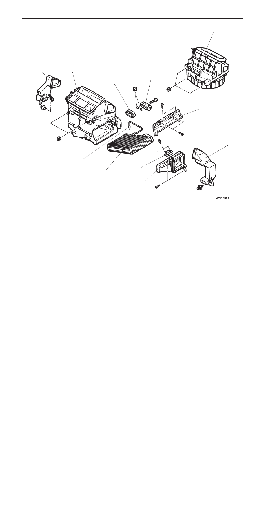
Heater Unit, Blower Unit,
Resister and Evaporator
55-23
10
12
11
15
16
14
19
13
21
14
18
17
10. Blower unit
14. Foot duct
19. Heater unit assembly
Evaporator and Resister removal
steps
D
Discharging and Charging of Re-
frigerant (Refer to P.55-10.)
D
Engine Cover (Refer to GROUP 11
– Engine Assembly.)
D
Air Cleaner
D
Glove Box (Refer to GROUP 52A
– Instrument Panel.)
11. Joint duct
12. Resistor
13. Cover
14. Foot duct
8. Refrigerant line connection
15. Expansion valve
16. Joint
17. Evaporator
18. Air thermosensor