Mitsubishi Pajero Pinin. Manual - part 365


  Index      Mitsubishi     Mitsubishi Pajero Pinin - service repair manual 2001 year


Search            


Content   ..  363  364  365  366   ..


Mitsubishi Pajero Pinin. Manual - part 365


HEATER, AIR CONDITIONER AND VENTILATION

 – 

On-vehicle Service

55-11

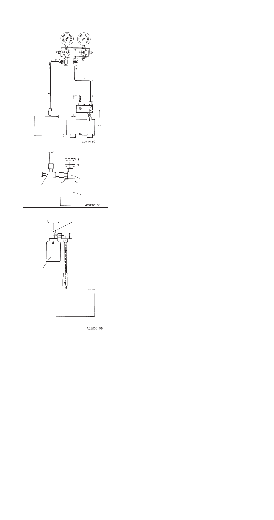
12. Turn the vacuum pump adaptor switch to the R-134a side

to start the vacuum pump.

Caution
Do not operate the compressor for evacuation.

13. Evacuate to a vacuum reading of 100 kPa or higher (takes

approx. 10 minutes).

14. Turn the vacuum pump adaptor switch OFF and allow

to stand it for 5 minutes.

Caution
Do not operate the compressor in the vacuum
condition; damage may occur.

15. Carry out a leak test. (Good if the negative pressure does

not drop.)

Caution
If the negative pressure drops, increase the tightness
of the connections, and then repeat the evacuation
procedure from step (12).

16. With the handle turned back all the way (valve open),

install the charging valve to the service can.

17. Turn the handle of the adaptor valve back all the way

(valve closed), remove it from the gauge manifold and
install the service can.

18. Tighten the handle of the charging valve (valve closed)

to puncture the service can.

19. Turn the handle of the charging valve back (valve open) and

tighten the handle of the adaptor valve (valve open) to
charge the system with refrigerant.

Caution
If the service can is inverted, liquid refrigerant may
be drawn into the compressor damaging it by liquid
compression. Keep the service can upright to ensure
that refrigerant is charged in gas state.

20. If the refrigerant is not drawn in, turn the handle of the

adaptor valve back all the way (valve closed).

21. Check for gas leaks using a leak detector.

If a gas leak is detected, re-tighten the connections, and
then repeat the charging procedure from evacuation in
step (12).

Caution
The leak detector for R-134a should be used.

22. Start the engine.
23. Operate the A/C and set to the lowest temperature (MAX.

COOL).

Low-pressure
service valve

Vacuum pump

Adaptor valve

Valve open

Valve close

Charging
valve

Service can

Charging valve

Service can
(Refrigerant
container)

Low-pressure
service valve

HEATER, AIR CONDITIONER AND VENTILATION

 – 

On-vehicle Service

55-12

24. Fix the engine speed at 1,500 r/min.
25. Tighten the handle of the adaptor valve (valve open) to

charge the required volume of refrigerant.

Caution
If the service can is inverted, liquid refrigerant may
be drawn into the compressor damaging it by liquid
compression. Keep the service can upright to ensure
that refrigerant is charged in gas state.

26. After charging with refrigerant, turn the handle of the

adaptor valve back all the way (valve closed).

27. Tighten the charging valve handle (valve closed).

Remove the quick joint (for low-pressure) from the
low-pressure service valve.

NOTE
If the service can is not emptied completely, keep the
handles of the charging valve and adaptor valve closed
for the next charging.

CORRECTING LOW REFRIGERANT LEVEL IN CASE THE
SERVICE CAN IS USED.

1.

Install the charge valve with the handle turned all the
way back (valve open) to the service can.

2.

Install the adaptor valve with the handle turned all the
way back (valve close) to the charging valve.

3.

Connect the charging hose (blue) to the adaptor valve.

4.

Connect the charging hose (blue) to the quick joint (for
low-pressure).

5.

Tighten the handle of the charge valve (valve close), and
pierce the service can.

6.

Turn the handle of the adaptor valve to bleed the air.

7.

Install the quick joint (for low-pressure) to the low-pressure
service valve.

NOTE
The low-pressure service valve should be connected to
the suction hose.

Valve open

Valve close

Service can
(Refrigerant
container)

Charge valve

Adaptor valve

Charging hose (blue)

Quick joint (for low-pressure)

Quick joint 
(for low-pressure)

Low-pressure
service valve

HEATER, AIR CONDITIONER AND VENTILATION

 – 

On-vehicle Service

55-13

8.

Start the engine.

9.

Operate the air conditioner and set at the lowest
temperature (MAX. COOL).

10. Fix the engine speed at 1,500 r/min.
11. Tighten the handle of the adaptor valve (valve open), and

replenish refrigerant while checking the quantity through
the sight glass.

Caution
If the service can is inverted, liquid refrigerant may
be draw into the compressor damaging it by liquid
compression. Keep the service can upright to ensure
that refrigerant is changed in gas state.

12. After replenishing is completed, turn the handle of the

adaptor valve all the way back (valve close), and remove
the quick joint.

NOTE
When there is remainder of refrigerant in the service can,
keep it for next use with the charge value and the valve
of the adaptor valve being closed.

DISCHARGING SYSTEM

1.

Run the engine at an engine speed of 1,200 – 1,500 r/min
for approximately 5 minutes with the A/C operating to
return to the oil.

NOTE
Returning the oil will be more effective if it is done while
driving.

2.

Stop the engine.

3.

Connect the charging hose (blue) to the adaptor valve
with its handle turned back all the way (valve closed).

4.

Connect the quick joint to the charging hose (blue).

5.

Install the quick joint to the low-pressure service valve.

NOTE
The low-pressure service valve should be connected to
the suction hose.

Caution
To connect the quick joint, press section “A” firmly
against the service valve until a click is heard.
When connecting, run your hand along the hose while
pressing to ensure that there are no bends in the hose.

6.

Place the adaptor valve inside the container and discharge
the refrigerant by opening the handle gradually so that
oil does not gush out.

NOTE
Any oil remaining in the container should be returned to
the A/C system.

Charging valve

Service can (Refriger-
ant container)

Low-pressure
service valve

Sleeve

Charging hose (blue)

Quick joint

Low-pressure
service valve

Oil

Adaptor valve

A

HEATER, AIR CONDITIONER AND VENTILATION

 – 

On-vehicle Service

55-14

REFILLING OF OIL IN THE A/C SYSTEM

Too little oil will provide inadequate compressor lubrication
and cause a compressor failure. Too much oil will increase
discharge air temperature.
When a compressor is installed at the factory, it contains 120
m

ȏ

 of refrigerant oil. While the A/C system is in operation,

the oil is carried through the entire system by the refrigerant.
Some of this oil will be trapped and retained in various parts
of the system.
When the following system components are changed, it is
necessary to add oil to the system to replace the oil being
removed with the component.

Compressor oil: ZXL 200PG

Quantity

Condenser: 10 m

ȏ


Evaporator: 40 m

ȏ


Suction hose: 6.5 m

ȏ

PERFORMANCE TEST

1.

The vehicles to be tested should be in a place that is
not in direct sunlight.

2.

Close the high and low-pressure valve of the gauge
manifold.

3.

Connect the charging hose (blue) to the low-pressure valve
and connect the charging hose (red) to the high-pressure
valve of the gauge manifold.

4.

Install the quick joint (for low-pressure) to the charging
hose (blue), and connect the quick joint (for high-pressure)
to the charging hose (red).

5.

Connect the quick joint (for low-pressure) to the
low-pressure service valve and connect the quick joint
(for high-pressure) to the high-pressure service valve.

NOTE
The high-pressure service valve is on liquid pipe A and
the low-pressure service valve is on the suction hose.

Caution
To connect the quick joint, press section “A” firmly
against the service valve until a click is heard.
When connecting, run your hand along the hose while
pressing to ensure that there are no bends in the hose.

6.

Start the engine.

Low-pressure valve

High-pressure valve

Gauge manifold

Charging
hose (red)

Charging
hose (blue)

Adaptor
valve (for low
pressure)

Sleeve

Adaptor valve
(for high pressure)

Low-
pressure
service
valve

High-
pressure
service
valve

A


Content   ..  363  364  365  366   ..