Mitsubishi Pajero Pinin. Manual - part 315


  Index      Mitsubishi     Mitsubishi Pajero Pinin - service repair manual 2001 year


Search            


Content   ..  313  314  315  316   ..


Mitsubishi Pajero Pinin. Manual - part 315


SRS – 

Air Bag Modules and Clock Spring

52B-39

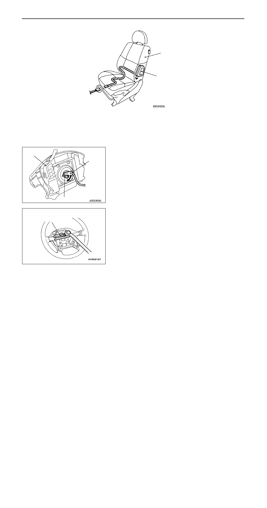
<Front seat back assembly with side air bag module (Vehicles with side air bag)>

1

Side air bag module

Removal

A

E

"

1. Front seat back assembly

Installation steps

"

A

A D

Pre-installation inspection

1. Front seat back assembly

D

Negative (–) battery cable connection

"

D

A D

Post-installation inspection

REMOVAL SERVICE POINTS

A

A

"

DRIVER’S AIR BAG MODULE REMOVAL

After removing the clip shown in the illustration, disconnect
the connector.

Caution
1.

The air bag module must not be measured with such
equipment as an ohmmeter, nor disassembled.

2.

The removed air bag module should be stored in a
clean, dry place with the deployment surface facing
up.

A

B

"

STEERING WHEEL REMOVAL

Caution
Do not hammer on the steering wheel. Doing so may
damage the collapsible column mechanism.

A

C

"

CLOCK SPRING REMOVAL

Caution
The removed clock spring should be stored in a clean,
dry place.

Air bag module

Connector

Clip

MB990803

SRS – 

Air Bag Modules and Clock Spring

52B-40

A

D

"

PASSENGER’S AIR BAG MODULE REMOVAL

Caution
The removed air bag module should be stored in a clean,
dry place with the deployment surface facing up.

A

E

"

FRONT SEAT BACK ASSEMBLY REMOVAL

Refer to GROUP 52A – Seat.
Caution
1.

When the side air bag module is required replacing,
replace the front seat back assembly.

2.

The removed front seat back assembly should be
stored in clean, dry place with its back touching the
ground.

INSTALLATION SERVICE POINTS

"

A

A

PRE-INSTALLATION INSPECTION

1.

Even new air bag modules and a clock spring require
inspection before installation. (Refer to P.52B-41.)

Caution
When discarding the air bag module or seat back
assembly, deploy the air bag as specified in the service
procedure. (Refer to P.52B-48.)

2.

Connect the negative (–) battery  terminal.

3.

Connect the MUT-

II

 to the diagnosis connector (16-pin).

Caution
Turn the ignition switch to LOOK (OFF) position when
connecting and disconnecting the MUT-

II

.

4.

Turn the ignition switch to ON.

5.

Read a diagnostic code to Refer to that the SRS is operating
properly except an open in the air bag module circuit.

6.

Turn the ignition switch to LOCK (OFF) position.
Disconnect the negative (–) battery cable and insulate
with tape.

Caution
Wait at least 60 seconds after the disconnection of the
battery cable before any further job. (Refer to P.52B-4.)

"

B

A

CLOCK SPRING INSTALLATION

Align the mating marks on the clock spring as mentioned in
the next step. Then, after putting the front wheels in
straight-ahead position, install the clock spring to the column
switch.

SRS – 

Air Bag Modules and Clock Spring

52B-41

Clock Spring Centring

Fully turn the clock spring clockwise and then turn it back
about 3 times counterclockwise to align the mating marks.

Caution
Unless the mating marks are properly aligned, the steering
wheel gets stuck amid a turn or the flat cable in the clock
spring is cut. These hinder the SRS air bag from proper
operation, resulting in serious injury to the vehicle’s driver.

"

C

A

STEERING WHEEL INSTALLATION

1.

Refer to first that the clock spring has been centred
properly. Then, install the steering wheel.

Caution
Be sure, when installing the steering wheel, not to
have the clock spring harness caught or tangled.

2.

After the installation, check the steering wheel for proper
operation by turning it fully right and left.

"

D

A

POST-INSTALLATION CHECK

1.

Lightly turn the steering wheel right and left to Refer to
that noise and malfunction are not present.

2.

Turn the ignition switch to “ON”.

3.

Does the SRS warning lamp illuminate for about 7 seconds
and then go out for 5 seconds or more?

4.

Yes: The SRS is working properly.
No: Go to Troubleshooting (Refer to P.52-8.)

INSPECTION

DRIVER’S AND PASSENGER’S AIR BAG MODULE
INSPECTION

If any malfunction is found in the following inspection, replace
the air bag module(s) with new one(s).
Discard the old one(s) after deployment as specified in the
service procedure. (Refer to P.52B-48.)

Caution
Never measure circuit resistance in the air bag modules
(squib) even with the specified tester. Measuring the circuit
resistance with a tester causes accidental air bag
deployment due to current that flows or static, resulting
in serious personal injury.

1.

Check the cover for dents, cracks or deformation.

2.

Check the connectors for damage, terminals for
deformation, and harness for binds.

3.

Check the air bag inflator cases for dents, cracks or
deformation.

4.

Install the driver’s air bag module to the steering wheel
and check fit or alignment with the steering wheel.

5.

Install the front passenger’s air bag module to instrument
panel and crossmember and check fit and alignment.

Mating marks

SRS warning lamp

<Driver’s side>

<Front passenger’s side>

Inflator case

Connector

Inflator
case

Connector

SRS – 

Air Bag Modules and Clock Spring

52B-42

Caution
If dents, cracks, deformation, or rust are present in
the air bag module(s), replace with new one(s).
Discard the old one(s) as specified in the service
procedure. (Refer to P.52B-48.)

CLOCK SPRING CHECK

If any malfunction is found in the following inspections, replace
the clock spring with a new one.
1.

Check the connectors and protective tubes for damage,
and terminals for deformation.

2.

Visually check the case for damage.

3.

Refer to that the clock spring has continuity between
connector No.2 and terminal No.4 of connector No.1.

4.

Remove the cover from the No. 3 connector of the clock
spring, and then insert the probes (MB991222).

Caution
The probe must not be inserted directly to the terminals
from the front of the connector.

5.

Connect a digital multimeter to the probe (MB991222),
as shown, to check that.

Standard value: 0.62 

±

 0.12 

FRONT SEAT BACK ASSEMBLY WITH SIDE AIR BAG
MODULE

If any malfunction is found in the following inspections, replace
the front seat back assembly.
To discard the removed front seat back assembly, deploy the
side air bag first as specified in the service procedure. (Refer
to P.52B-48.)

Case

Protective tubes

1

2

3

Clock spring

Probe
(MB991222)

3

2

Digital
multimeter

3

Cover

Side air bag module
deployment section


Content   ..  313  314  315  316   ..