Mitsubishi Pajero Pinin. Manual - part 251
ABS <4WD> –
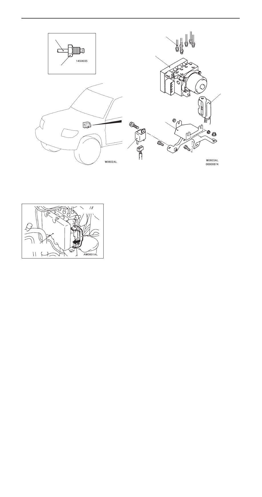
Hydraulic Unit and ABS-ECU
35B-27
<R.H. drive vehicles>
15 Nm
2
3
1
4
3
5
Removal steps
1. ABS warning lamp relay
A
A
"
2. Harness connector
"
A
A
3. Brake pipe connection
A
B
"
4. Hydraulic unit and ABS-ECU
5. Hydraulic unit bracket assembly
REMOVAL SERVICE POINTS
A
A
"
HARNESS CONNECTOR DISCONNECTION
Move the lock lever of the ABS-ECU connector as shown
in the illustration, and then disconnect the harness connector.
Hydraulic unit
and ABS-ECU
Lock lever