Mitsubishi Pajero Pinin. Manual - part 249


  Index      Mitsubishi     Mitsubishi Pajero Pinin - service repair manual 2001 year


Search            


Content   ..  247  248  249  250   ..


Mitsubishi Pajero Pinin. Manual - part 249


ABS <4WD> – 

Troubleshooting

35B-19

DATA LIST REFERENCE TABLE

The following items can be read by the MUT-

II

 from the ABS-ECU input data.

1.

When the system is normal

Item No.

Check item

Checking requirements

Normal value

11

Front-right wheel speed sensor

Perform a test run

Vehicle speeds
displayed on the

12

Front-left wheel speed sensor

displayed on the
speedometer
and MUT

II

are

13

Rear-right wheel speed sensor

and  MUT-

II

 are

identical.

14

Rear-left wheel speed sensor

16

ABS-ECU power supply 
voltage

Ignition switch: ON

9.2 – 17.5 V

32

G sensor

Vehicle is stopped.

2.4 – 2.6 V

Vehicle is running.

0.5 – 4.5 V

33

Stop lamp switch

Depress the brake pedal.

ON

Release the brake pedal.

OFF

2.

When the ABS-ECU shut off ABS operation.

When the diagnosis system stops the ABS-ECU, the MUT-

II

 display data will be unreliable.

ACTUATOR TEST REFERENCE TABLE

The MUT-

II

 activates the following actuators for testing.

NOTE
1.

If the ABS-ECU runs down, actuator testing cannot be carried out.

2.

Actuator testing is only possible when the vehicle is stationary.

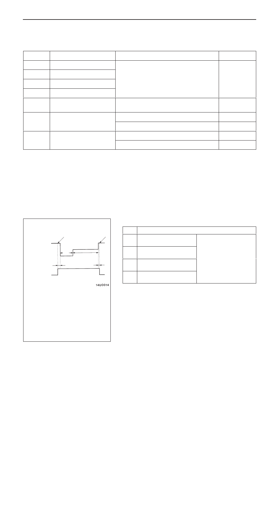
ACTUATOR TEST SPECIFICATIONS

No.

Item

01

Solenoid valve for
front-right wheel

Solenoid valves and pump
motors in the hydraulic unit
(simple inspection mode)

02

Solenoid valve for front-left
wheel

(simple inspection mode)

03

Solenoid valve for rear-right
wheel

04

Solenoid valve for rear-left
wheel

2s

1s

Activation pattern

Solenoid
valve

Pump
motor

ON

OFF

Start of 
forced
action

End of forced
action

A

B

C

0.05 s

0.01 s

NOTE

A: Hydraulic pressure increase
B: Hydraulic pressure holds
C: Hydraulic pressure decrease

ABS <4WD> – 

Troubleshooting

35B-20

CHECK AT ABS-ECU

TERMINAL VOLTAGE CHECK CHART

1.

Disconnect the ABS-ECU connector. (Refer to P. 35B-27.)

2.

Use the special tool to measure the voltage between each
terminal and earth (terminal No.23).

3.

The terminal layout is shown in the illustration.

Terminal No.

Check item

Checking requirements

Normal condition

3

Stop lamp switch input

Ignition switch: ON

Stop lamp switch: ON

System voltage

Stop lamp switch: OFF

1 V or less

7

Input from G sensor

Ignition switch: ON

2.4 – 2.6 V

7

In ut from G sensor

Ignition switch: ON
Vehicle is horizontal

2.4   2.6 V

8

ABS warning lamp 
relay transistor output

Ignition switch: ON

When the lamp is
switched off

2 V or less

When the lamp is illu-
minated

System voltage

9

MUT-

II

When the MUT-

II

 is connected

Serial communication
with MUT-

II

When the MUT-

II

 is not connected

1 V or less

10

ABS-ECU power 
supply

Ignition switch: ON

System voltage

supply

Ignition switch: START

0 V

19

Diagnosis changeover
input

When the MUT-

II

 is connected

0 V

input

When the MUT-

II

 is not connected

Approx. 12 V

20

G sensor earth

Always

0 V

22

Solenoid valve power
supply

Always

System voltage

24

Motor power supply

Always

System voltage

Check connector

MB991547

ABS-ECU

Body side harness

Earth terminal

ABS <4WD> – 

Troubleshooting

35B-21

RESISTANCE AND CONTINUITY BETWEEN
HARNESS-SIDE CONNECTOR TERMINALS

1.

Turn the ignition key to the LOCK (OFF) position.

2.

Disconnect the ABS-ECU connector. (Refer to P. 35B-27.)

3.

Use the special tool to check the resistance and continuity
between the terminals indicated in the table below.

4.

The terminal layout is shown in the illustration.

ABS–ECU terminal No.

Signal

Normal condition

1 – 2

Wheel speed sensor (rear left)

1.30 – 1.58 k

4 – 5

Wheel speed sensor (rear right)

14 – 15

Wheel speed sensor (front left)

17 – 18

Wheel speed sensor (front right)

21 – Body earth

Earth

Continuity

23 – Body earth

Earth

Check connector

MB991547

ABS-ECU

Body side harness

ABS <4WD> – 

On-vehicle Service

35B-22

ON-VEHICLE SERVICE

WHEEL SPEED SENSOR OUTPUT VOLTAGE
CHECK

1.

Lift up the vehicle and release the parking brake.

2.

Disconnect the ABS-ECU connector and then connect
the special tool to the harness side connector. (Refer to
P. 35B-27.)

3.

Rotate the wheel to be measured at approximately 1/2 – 1
rotation per second, and check the output voltage using a
circuit tester or an oscilloscope.

Wheel speed
sensor

Front
left

Front
right

Rear left

Rear
right

Terminal No.

15

17

2

4

14

18

1

5

Output voltage

When measuring with a circuit tester:

42 mV or more

When measuring with an oscilloscope:

120 mV p-p or more

4.

The followings are suspected if the output voltage is lower
than the value described above. Check the wheel speed
sensor, and replace if necessary.

D

Too large clearance between the pole piece of the
wheel speed sensor and ABS rotor

D

Faulty wheel speed sensor

Inspecting Waveforms With An Oscilloscope

Use the following method to observe the output voltage
waveform from each wheel speed sensor with an oscilloscope.

D

Start the engine, and rotate the rear wheels by engaging
1st gear (vehicles with manual transmission) or D range
(vehicles with automatic transmission). Turn the front
wheels manually so that they rotate at a constant speed.

NOTE
1.

The waveform measurements can also be taken while
the vehicle is actually moving.

2.

The output voltage will be small when the wheel speed
is low, and similarly it will be large when the wheel speed
is high.

Check connector

MB991547

ABS-ECU

Body side harness

When turning by hand

When idling (5 – 6 km/h), 1st gear (M/T)
or D range (A/T)

10.0 ms/DIV 1

V/DIV


Content   ..  247  248  249  250   ..