Mitsubishi Pajero Pinin. Manual - part 237
BASIC BRAKE SYSTEM –
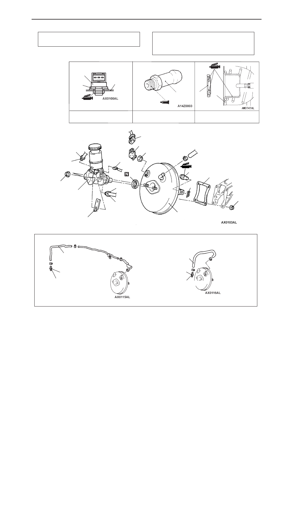
Master Cylinder and Brake Booster
35A-16
<L.H. drive vehicles without ABS and R.H. drive vehicles>
Pre-removal Operation
Brake Fluid Draining
Post-installation Operation
D
Brake Fluid Supplying and Air Bleeding
(Refer to P.35A-10.)
D
Brake Pedal Adjustment (Refer to P.35A-6.)
Specified Sealant: 3M ATD
Part No.8661 or equivalent
Grease: Silicone grease
11
4
7
8
14
9
10
1
2
12
12 Nm
15 Nm
14 Nm
15 Nm
1
3
11
6
14
14.7 – 17.7 Nm
12
10
5
13
<L.H. drive vehicles>
14
<R.H. drive vehicles>
14.7 – 17.7 Nm
6
Grease: Silicone grease
12
4