Mitsubishi Pajero Pinin. Manual - part 125
MPI <4G9> –
Troubleshooting
13C-86
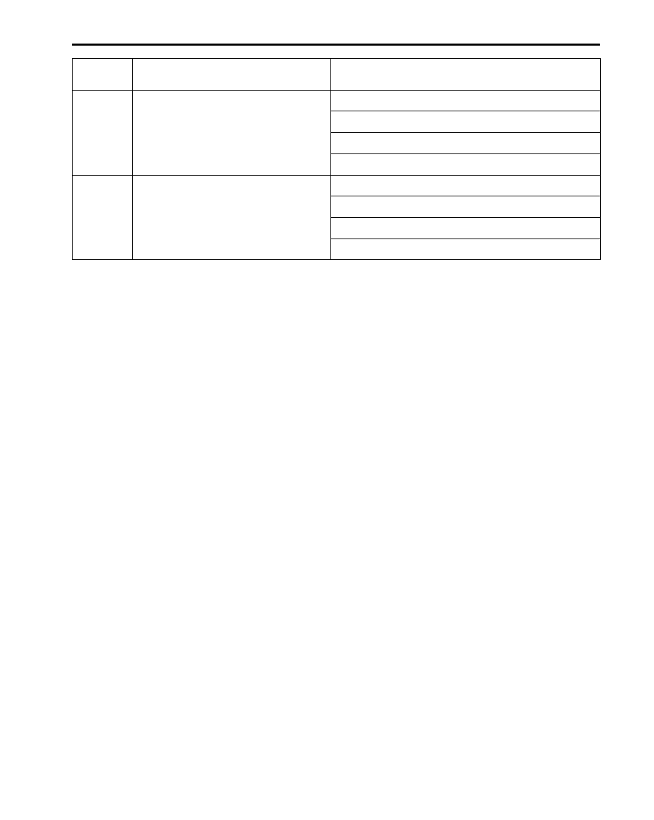
Terminal
No.
Normal condition (Check condition)
Inspection item
72 – 92
Intake air temperature sensor
5.3 – 6.7 k
Ω
(When intake air temperature is 0
_
C)
2.3 – 3.0 k
Ω
(When intake air temperature is 20
_
C)
1.0 – 1.5 k
Ω
(When intake air temperature is 40
_
C)
0.30 – 0.42 k
Ω
(When intake air temperature is 80
_
C)
83 – 92
Engine coolant temperature sensor
5.1 – 6.5 k
Ω
(When coolant temperature is 0
_
C)
2.1 – 2.7 k
Ω
(When coolant temperature is 20
_
C)
0.9 – 1.3 k
Ω
(When coolant temperature is 40
_
C)
0.26 – 0.36 k
Ω
(When coolant temperature is 80
_
C)