Mitsubishi Pajero Pinin. Manual - part 52
GDI –
Troubleshooting
13A-74
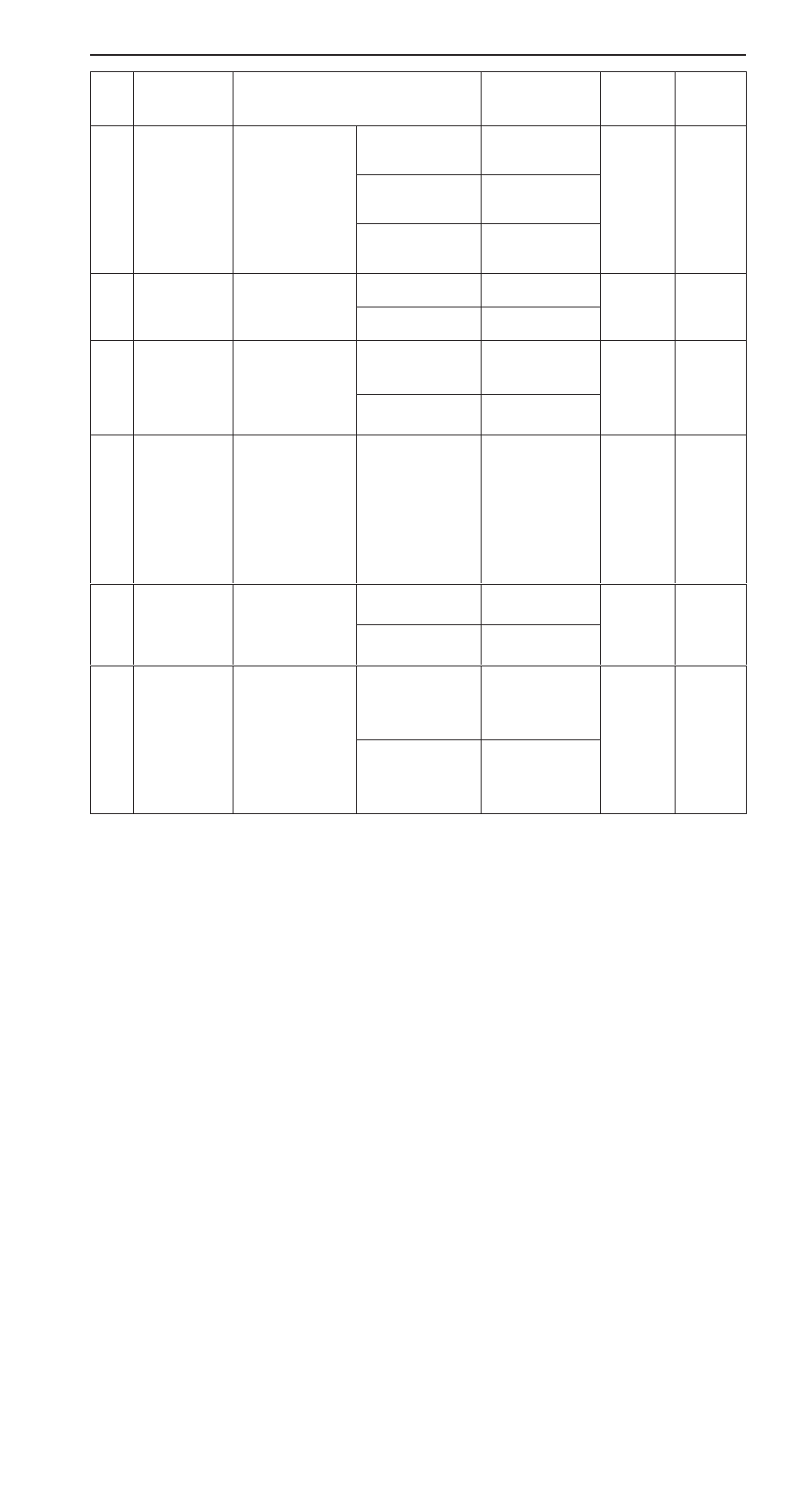
Item
No.
Refer-
ence
page
Inspection
procedure
No.
Normal condition
Requirements
Check items
41
Injector drive
time *
2
D
Engine coolant
temperature: 80
– 95
_
C
L
l
t i
Idling
0.5 – 0.7 ms*
1
Code
No.41
13A-25
D
Lamps, electric
cooling fan and
all accessories:
OFF
2,500 r/min
0.4 – 0.8 ms
OFF
D
Transmission:
Neutral (A/T: P
range)
Sudden racing
Increases
44
Ignition
advance
D
Engine: After
warm-up
Idling
12 – 20
_
BTDC *
2
Code
No.44
13A-27
advance
warm u
D
Set a timing
light.
2,500 r/min
20 – 40
_
BTDC
No.44
49
A/C relay
Engine: After warm-
up, idling
A/C switch: OFF
OFF (compressor
clutch is not oper-
ating)
Procedure
No.32
13A-69
A/C switch: ON
ON (compressor
clutch is operating)
66
Brake vacuum
sensor
D
Engine coolant
temperature: 80
– 95
_
C
D
Lamps, electric
cooling fan and
all accessories:
OFF
D
Transmission:
Neutral
(A/T: P range)
Stop the engine
from idling speed,
and then depress
the brake pedal
several times with
the ignition switch
on.
Displayed pres-
sure increases.
Code
No.66
13A-32
67
Stop lamp
switch
Ignition switch: ON
Brake pedal:
Depressed
OFF
Procedure
No.33
13A-70
Brake pedal:
Released
ON
68
EGR valve
D
Engine coolant
temperature: 80
– 95
_
C
D
Lamps, electric
cooling fan and
Idling
0 – 15 STEP
Procedure
No.29
13A-67
cooling fan and
all accessories:
OFF
D
Transmission:
Neutral
(A/T: P range)
2,500 r/min
0 – 10 STEP