Mitsubishi Pajero Pinin. Manual - part 46


  Index      Mitsubishi     Mitsubishi Pajero Pinin - service repair manual 2001 year


Search            


Content   ..  44  45  46  47   ..


Mitsubishi Pajero Pinin. Manual - part 46


GDI – 

Troubleshooting

13A-50

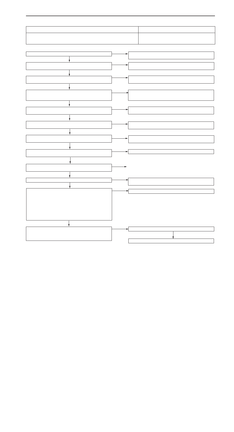
INSPECTION PROCEDURE 9

When the engine is cold, it stalls at idling. (Die out)

Probable cause

The cause is probably an incorrect air/fuel ratio or poor intake air amount when
the engine is cold.

D

Malfunction of the electronic-control throttle valve
system

D

Malfunction of the throttle body

Have the battery terminals been disconnected recently?

Yes

Warm up the engine, and then let it run at idle for approx. ten
minutes.

No

MUT-

II

 Self-Diag code

Is a diagnosis code displayed?

Yes

Refer to P.13A-14, INSPECTION CHART FOR DIAGNOSIS
CODES.

No

Is the engine idling correct after the engine has been warmed
up?

Yes

Refer to “Unstable idling (rough idle, hunting).” (Refer to P.13A-47,
INSPECTION PROCEDURE 7.)

No

MUT-

II

 Data list

22 Crank angle sensor (Refer to P.13A-72.)

Check idling speed when the engine is cold.

NG

Check the throttle valve position feedback system. (Refer to
P.13A-37, INSPECTION PROCEDURE FOR DIAGNOSIS CODE
92.)

OK

MUT-

II

 Data list

26 Accelerator pedal position switch (Refer to P.13A-73.)

NG

Check the accelerator position switch. (Refer to P.13A-65, IN-
SPECTION PROCEDURE 27.)

OK

MUT-

II

 Data list

21 Engine coolant temperature sensor (Refer to P.13A-72.)

NG

Check the engine coolant temperature sensor. (Refer to P.13A-19,
INSPECTION PROCEDURE FOR DIAGNOSIS CODE 21.)

OK

MUT-

II

 Data list

68 EGR valve (Refer to P.13A-74.)

NG

Check the EGR valve system. (Refer to P.13A-67, INSPECTION
PROCEDURE 29.)

OK

Does the engine stall immediately after the accelerator pedal is
released?

Yes

Clean around the throttle valve. (Refer to P.13A-92.)

No

Measure fuel high pressure between the fuel pump (high pressure)
and injector. (Refer to P.13A-97.)

NG

Repair

OK

Check ignition timing. (Refer to GROUP 11A – Engine Adjustment.)

NG

Check that the crank angle sensor and timing belt cover are proper-
ly installed.

OK

Check ignition coil spark for each cylinder.
(1) Remove the ignition coil.
(2) Install a new spark plug to the removed ignition coil.
(3) Disconnect the injector intermediate connector.

Caution
Never touch the connector terminal as approx. 100 V is
applied to the injector, or you are seriously injured.

(4) Earth the spark plug electrode securely.
(5) Check that the spark plug ignites when the engine is cranked.

NG

Replace the ignition coil.

OK

Check all the following items:

D

Spark plugs

D

Compression pressure

D

Engine oil viscosity

NG

Check trouble symptom.

OK

Replace the injector.

GDI – 

Troubleshooting

13A-51

INSPECTION PROCEDURE 10

When the engine is hot, it stalls at idling. (Die out)

Probable cause

The cause is probably an improper air/fuel ratio, faulty electronic-controlled throttle
valve system, compression pressure. In addition, if the engine stalls suddenly, another
possible cause might be a poor connector contact.

D

Malfunction of the ignition system

D

Malfunction of air/fuel ratio control system

D

Malfunction of electronic-controlled throttle valve
system

D

Malfunction of the throttle body

D

Poor connector contact

D

Improper compression pressure

D

Air stuck in the air intake system

NG

Repair

Have the battery terminals been disconnected recently?

Yes

Warm up the engine, and then let it run at idle for approx. ten
minutes.

No

MUT-

II

 Self-Diag code

Is a diagnosis code displayed?

Yes

Refer to P.13A-14, INSPECTION CHART FOR DIAGNOSIS
CODES.

No

MUT-

II

 Data list

79 Throttle position sensor (1st channel) (Refer to P.13A-75.)

NG

Check the throttle position sensor (1st channel) system. (Refer
to P.13A-35, INSPECTION PROCEDURE FOR DIAGNOSIS
CODE 79.)

OK

Is it easy to reproduce the engine stall?

No

While carrying out an intermittent malfunction simulation test. (Re-
fer to GROUP 00 – Points to Note for Intermittent Malfunction.),
check for sudden changes in the following signals.

D

Crank angle sensor signal

D

Injector drive signal

D

Fuel pump (low pressure) drive signal

D

Air flow sensor

D

Primary ignition signal

D

Power supply to the engine-ECU

Yes

MUT-

II

 Data list

26 Accelerator pedal position switch (Refer to P.13A-73.)

NG

Check the accelerator pedal position switch. (Refer to P.13A-65,
INSPECTION PROCEDURE 27.)

OK

MUT-

II

 Data list

13 Intake air temperature sensor (Refer to P.13A-71.)

NG

Check the intake air temperature sensor. (Refer to P.13A-17, IN-
SPECTION PROCEDURE FOR DIAGNOSIS CODE 13.)

OK

MUT-

II

 Data list

25 Barometric pressure sensor (Refer to P.13A-73.)

NG

Check the barometric pressure sensor. (Refer to P.13A-23, IN-
SPECTION PROCEDURE FOR DIAGNOSIS CODE 25.)

OK

MUT-

II

 Data list

21 Engine coolant temperature sensor (Refer to P.13A-72.)

NG

Check the engine coolant temperature sensor. (Refer to P.13A-19,
INSPECTION PROCEDURE FOR DIAGNOSIS CODE 21.)

MUT-

II

 Data list

11 Oxygen sensor
OK: 600 – 1,000 mV when the engine is suddenly raced

NG

Check the oxygen sensor system. (Refer to P.13A-15, INSPEC-
TION PROCEDURE FOR DIAGNOSIS CODE 11.)

OK

MUT-

II

 Data list

11 Oxygen sensor

OK: 0 – 400 mV and 600 – 1,000 mV alternates when the

engine is idling (wait for four minutes after the engine
started).

NG

Measure fuel high-pressure between the fuel pump (high pressure)
and injector. (Refer to P.13A-97.)

OK

Check that air is sucked in the air intake system.

D

Broken intake manifold gasket

D

Damaged vacuum hose

D

Damaged air intake hose

OK

To the next page

OK

GDI – 

Troubleshooting

13A-52

From the previous page

OK

MUT-

II

 Data list

27 Power steering fluid pressure switch (Refer to P.13A-73.)

NG

Check the power steering fluid pressure switch system. (Refer
to P.13A-69, INSPECTION PROCEDURE 31.)

OK

MUT-

II

 Data list

28 A/C switch (Refer to P.13A-73.)

NG

Check the A/C switch and A/C relay system. (Refer to P.13A-69,
INSPECTION PROCEDURE 32.)

MUT-

II

 Data list

29 Inhibitor switch (Refer to P.13A-73.)

NG

Check the ignition switch-ST and inhibitor switch <A/T>. (Refer
to P.13A-64, INSPECTION PROCEDURE 26.)

OK

MUT-

II

 Data list

34 Air flow sensor reset signal (Refer to P.13A-73.)

NG

Check the air flow sensor system. (Refer to P.13A-16, INSPEC-
TION PROCEDURE FOR DIAGNOSIS CODE 12.)

OK

MUT-

II

 Data list

68 EGR valve (Refer to P.13A-74.)

NG

Check the EGR valve system. (Refer to P.13A-67, INSPECTION
PROCEDURE 29.)

OK

Yes

Clean around the throttle valve. (Refer to P.13A-92.)

No

NG

Check that the crank angle sensor and timing belt cover are proper-
ly installed.

OK

Check ignition coil spark for each cylinder.
(1) Remove the ignition coil.
(2) Install a new spark plug to the removed ignition coil.
(3) Disconnect the injector intermediate connector.

Caution
Never touch the connector terminal as approx. 100 V is
applied to the injector, or you are seriously injured.

(4) Earth the spark plug electrode securely.
(5) Check that the spark plug ignites when the engine is cranked.

NG

Replace the ignition coil.

OK

Check all the following items:

D

Spark plugs

D

Compression pressure

D

Foreign material (such as water or kerosine) entered the fuel
lines

MUT-

II

 Data list

31 Small lamp switch (Refer to P.13A-73.)

Check the small lamp switch system. (Refer to P.13A-70, INSPEC-
TION PROCEDURE 34.)

OK

OK

NG

Check ignition timing. (Refer to GROUP 11A – Engine Adjustment.)

Does the engine stall immediately after the accelerator pedal is
released?

GDI – 

Troubleshooting

13A-53

INSPECTION PROCEDURE 11

The engine stalls when starting the car. (Pass out)

Probable cause

The cause is probably poor ignition due to a malfunctioning spark plug (weak spark),
or an incorrect air/fuel ratio when the accelerator is depressed.

D

Malfunction of the ignition system

D

Malfunction of the EGR valve

D

Air stuck in the air intake system

MUT-

II

 Self-Diag code

Is a diagnosis code displayed?

Yes

Refer to P.13A-14, INSPECTION CHART FOR DIAGNOSIS
CODES.

No

MUT-

II

 Data list

68 EGR valve (Refer to P.13A-74.)

NG

Check the EGR valve system. (Refer to P.13A-67, INSPECTION
PROCEDURE 29.)

OK

MUT-

II

 Actuator test

08 Purge control solenoid valve (Refer to P.13A-76.)

NG

Check the purge control solenoid valve system. (Refer to P.13A-68,
INSPECTION PROCEDURE 30.)

OK

Check ignition coil spark for each cylinder.
(1) Remove the ignition coil.
(2) Install a new spark plug to the removed ignition coil.
(3) Disconnect the injector intermediate connector.

Caution
Never touch the connector terminal as approx. 100 V is
applied to the injector, or you are seriously injured.

(4) Earth the spark plug electrode securely.
(5) Check that the spark plug ignites when the engine is cranked.

NG

Replace the ignition coil.

OK

Check all the following items:
(1) Spark plug
(2) Check if air is stuck in the air intake system.

D

Damage intake manifold gasket

D

Damaged or disconnected vacuum hose

D

Damaged air intake hose


Content   ..  44  45  46  47   ..