Mitsubishi Pajero Pinin. Manual - part 44
GDI –
Troubleshooting
13A-42
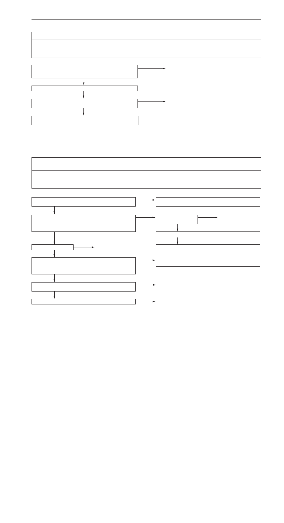
INSPECTION PROCEDURE 2
MUT-
II
communication with engine-ECU is impossible.
Probable cause
This may be caused by malfunction of engine-ECU power supply circuit and earth
circuit.
D
Malfunction of engine-ECU power supply circuit
D
Malfunction of engine-ECU
D
Open circuit between the engine-ECU and diagnosis
connector
NG
Check the harness wire between engine-ECU and diagnosis con-
nector.
NG
Repair
OK
Check trouble symptom.
Check the following connectors:
C-53 <Vehicles with multi center display>, C-19, C-28, C-35,
C-70
NG
Repair
OK
Check the engine-ECU power supply and earth circuit system. (Refer
to P.13A-62, INSPECTION PROCEDURE 23.)
NOTE
On vehicles with multi center display, if a malfunction cannot be resolved after the procedure above, check
the multi center display and replace if necessary. (Refer to GROUP 54 – Multi center display.)
INSPECTION PROCEDURE 3
The engine warning lamp does not illuminate right after
the ignition switch is turned to the ON position.
Probable cause
Because there is a burnt-out bulb, the engine-ECU causes the engine warning lamp
to illuminate for five seconds immediately after the ignition switch is turned to ON.
If the engine warning lamp does not illuminate immediately after the ignition switch
is turned to ON, one of the malfunctions listed at right has probably occurred.
D
Burnt-out bulb
D
Defective warning lamp circuit
D
Malfunction of the engine-ECU
MUT-
II
Data list
16 Engine-ECU power supply voltage (Refer to P.13A-72.)
NG
Check the engine-ECU power supply and earth circuit system.
(Refer to P.13A-62, INSPECTION PROCEDURE 23.)
OK
Measure at the engine-ECU connector C-17.
D
Disconnect the connector, and measure at the harness side.
D
Earth the terminal No. 31.
OK: The engine warning lamp illuminates.
OK
Check the following
connector: C-17
NG
Repair
OK
Check trouble symptom.
NG
Replace the engine-ECU.
NG
Check a burnt-out bulb.
NG
Replace
OK
Measure at the combination meter connector C-06.
D
Disconnect the connector, and measure at the harness side.
D
Voltage between 1 and earth (Ignition switch: ON)
OK: System voltage
NG
Check the engine warning lamp power supply circuit, and repair
if necessary.
OK
Check the following connectors:
C-06, C-07, C-17, C-28
NG
Repair
OK
Check trouble symptom.
NG
Check the harness wire between combination meter and engine-
ECU, and repair if necessary.