Mitsubishi Space Star. Manual - part 120


  Index      Mitsubishi     Mitsubishi Space Star - service repair manual 2000 year


Search            


Content   ..  118  119  120  121   ..


Mitsubishi Space Star. Manual - part 120


AUTOMATIC TRANSMISSION – 

On-vehicle Service

23-47

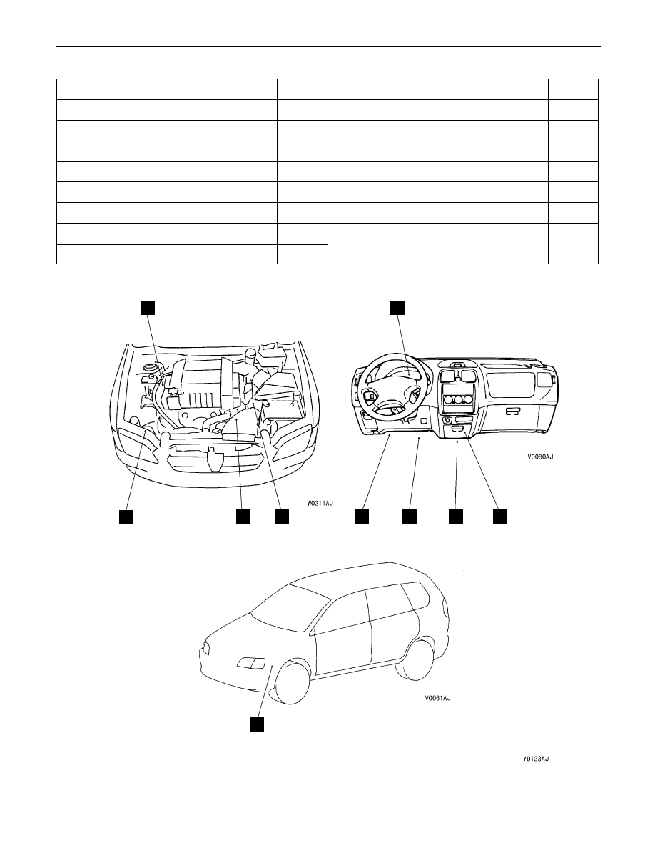
A/T CONTROL COMPONENT LOCATION

Name

Symbol

Name

Symbol

Accelerator position sensor

J

Input shaft speed sensor

D

A/T control relay

I

A/T fluid temperature sensor

D

A/T control solenoid valve assembly

D

Output shaft speed sensor

D

Crank angle sensor

A

Shift indicator lamp

E

Diagnosis connector

H

Stop lamp switch

F

Dual pressure switch

B

Vehicle speed sensor

D

Engine-A/T-ECU

I

Wide open throttle switch

G

Inhibitor switch

C

A

B

C

D

E

F

G

H

I

J

AUTOMATIC TRANSMISSION – 

On-vehicle Service

23-48

A/T CONTROL COMPONENT CHECK

CRANK ANGLE SENSOR CHECK

Refer to GROUP 13A – Troubleshooting.

ACCELERATOR PEDAL POSITION SENSOR CHECK 

Refer to GROUP 13A – On-vehicle Service.

A/T fluid TEMPERATURE SENSOR CHECK

1.

Remove the A/T fluid temperature sensor.

2.

Measure the resistance between terminals No. 1 and No.
2 of the oil temperature sensor connector.

Standard value:

Oil temperature (


C)

Resistance (k

)

0

16.7 – 20.5

20

7.3 –  8.9

40

3.4 –  4.2

60

1.9 – 2.2

80

1.0 – 1.2

100

0.57 – 0.69

INHIBITOR SWITCH CHECK

Refer to P.23A-45.

STOP LAMP SWITCH CHECK

Refer to GROUP 35 – Brake Pedal.

VEHICLE SPEED SENSOR CHECK

Refer to GROUP 54 – On-vehicle Service.

DUAL PRESSURE SWITCH CHECK

Refer to GROUP 55 – On-vehicle Service.

WIDE OPEN THROTTLE SWITCH CHECK

Refer to P.23-63.

Oil temperature sensor

AT F

AUTOMATIC TRANSMISSION – 

On-vehicle Service

AUTOMATIC TRANSMISSION – 

On-vehicle Service

23-49

A/T CONTROL RELAY CHECK

1.

Remove the A/T control relay.

2.

Use jumper wires to connect A/T control relay terminal
2 to the battery (–) terminal and terminal 4 to the battery
(+) terminal.

3.

Check the continuity between terminal 1 and terminal 3
of the A/T control relay when the jumper wires are
connected to and disconnected from the battery.

Jumper wire

Continuity between terminals No. 1
and No. 3

Connected

Continuity

Disconnected

No continuity

4.

If there is a problem, replace the A/T control relay.

SOLENOID VALVE CHECK

1.

Remove the valve body cover.

2.

Disconnect the connectors of each solenoid valve.

3.

Measure the resistance between terminals 1 and 2 of
each solenoid valve.

Standard value:

Name

Resistance

Damper clutch solenoid valve

2.7 – 3.4 


( t 20


C)

Low and reverse solenoid valve

(at 20


C)

Second solenoid valve

Underdrive solenoid valve

Overdrive solenoid valve

4.

If the resistance is outside the standard value, replace
the solenoid valve.

A/T control relay

Overdrive
solenoid
valve

Low and
reverse
solenoid
valve

Second
solenoid
valve

Damper
clutch
solenoid
valve

Underdrive
solenoid
valve

AUTOMATIC TRANSMISSION – 

On-vehicle Service

23-50

TORQUE CONVERTER STALL TEST

This test measures the maximum engine speed when the
selector lever is at the D or R position and the torque converter
stalls to test the operation of the torque converter (stator and
one-way clutch operation) and the holding performance of
the clutches and brakes in the transmission.

Caution
Do not let anybody stand in front of or behind the vehicle
while this test is being carried out.

1.

Check the A/T fluid level and temperature and the engine
coolant temperature.


Fluid level: At the HOT mark on the oil level gauge


A/T fluid temperature: 70 – 80


C


Engine coolant temperature: 80 – 100


C

2.

Check both rear wheels (left and right).

3.

Pull the parking brake lever on, with the brake pedal fully
depressed.

4.

Start the engine.

5.

Move the selector lever to the D position, fully depress
the accelerator pedal and take a reading of the maximum
engine speed at this time.

Caution
(1) The throttle should not be left fully open for any

more than eight seconds.

(2) If carrying out the stall test two or more times,

move the selector lever to the N position and run
the engine at 1,000 r/min to let the automatic
transmission fluid cool down before carrying out
subsequent tests.

Standard value

Stall speed: 2,200 – 2,700 r/min

6.

Move the selector lever to the R position and carry out
the same test again.

Standard value

Stall speed: 2,200 – 2,700 r/min

TORQUE CONVERTER STALL TEST JUDGEMENT
RESULTS

1.

Stall speed is too high in both D and R ranges


Low line pressure


Low & reverse brake slippage

2.

Stall speed is too high in D range only


Underdrive clutch slippage

3.

Stall speed is too high in R range only


Reverse clutch slippage

4.

Stall speed too low in both D and R ranges


Malfunction of torque converter


Insufficient engine output

Reverse
clutch

Low-reverse
brake

Underdrive
clutch

Torque
converter


Content   ..  118  119  120  121   ..