Mitsubishi Space Star. Manual - part 73


  Index      Mitsubishi     Mitsubishi Space Star - service repair manual 2000 year


Search            


Content   ..  71  72  73  74   ..


Mitsubishi Space Star. Manual - part 73


MPI  – 

On-vehicle Service

13B-79

NOTE
Unless the ISC servo is released, the Actuator test mode
will continue 27 minutes.

8.

Switch OFF the ignition switch.

9.

Disconnect the MUT-

II.

10. Start the engine again and let it run at idle speed for

about 10 minutes; check that the idling condition is normal.
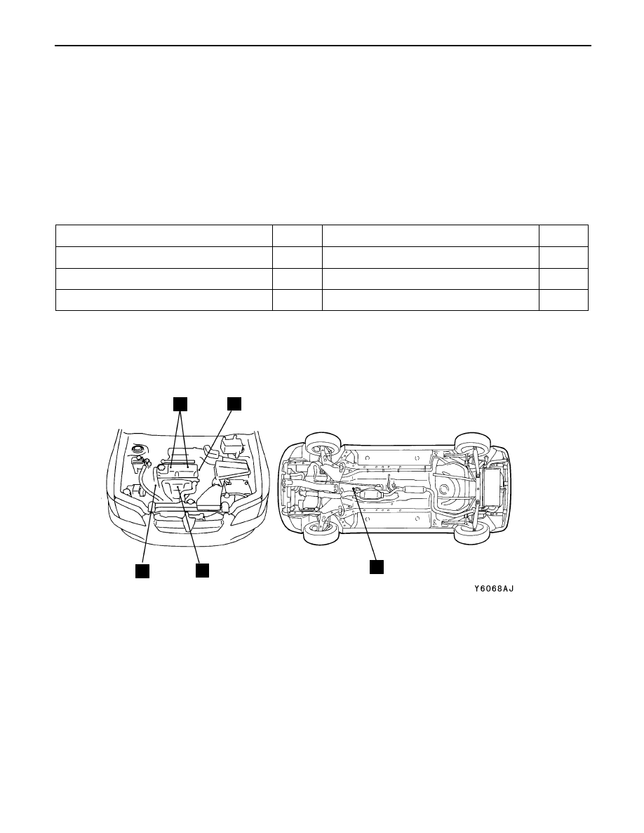
COMPONENT LOCATION

Name

Symbol

Name

Symbol

Camshaft position sensor

B

Ignition failure sensor

B

Crank angle sensor

C

Oxygen sensor (front)

D

Ignition coil

A

Oxygen sensor (rear)

E

C

B

A

D

E

MPI  – 

On-vehicle Service

13B-80

INTAKE AIR TEMPERATURE SENSOR CHECK

1.

Disconnect the vacuum sensor connector.

2.

Measure resistance between terminals 1 and 3.

Standard value:

2.3  – 3.0 k

 (at 20


C)

0.30  – 0.42 k

 (at 80


C)

3.

Remove the vacuum sensor.

4.

Measure resistance while heating the sensor using a hair
drier.

Normal condition:

Temperature (


C)

Resistance (k

)

Higher

Smaller

5.

If the value deviates from the standard value or the
resistance remains unchanged, replace the vacuum
sensor.

6.

Install the vacuum sensor and tighten it to the specified
torque.

Tightening torque: 13 – 15 Nm

OXYGEN SENSOR CHECK

<Oxygen sensor (front)>

1.

Disconnect the oxygen sensor connector and connect the
special tool (test harness) to the connector on the oxygen
sensor side.

2.

Make sure that there is continuity (4.5 – 8.0 

 at 20


C)

between terminal 1 (red clip of special tool) and terminal
3 (blue clip of special tool) on the oxygen sensor connector.

3.

If there is no continuity, replace the oxygen sensor.

4.

Warm up the engine until engine coolant is 80


C or higher.

Equipment side connector

Vacuum
sensor

Vacuum sensor

Equipment
side connector

Oxygen sensor

Blue

Red

MD998464

Oxygen
sensor
equip-
ment side
connector

MPI  – 

On-vehicle Service

13B-81

5.

Use a jumper wire to connect terminal 1 (red clip) of the
oxygen sensor connector to the battery (+) terminal and
terminal 3 (blue clip) to the battery (–) terminal.

Caution
Be very careful when connecting the jumper wire;
incorrect connection can damage the oxygen sensor.

6.

Connect a digital voltage meter between terminal 2 (black
clip) and terminal 4 (white clip).

7.

While repeatedly racing the engine, measure the oxygen
sensor output voltage.

Standard value:

Engine

Oxygen sensor
output voltage

Remarks

When
racing the
engine

0.6 – 1.0 V

If you make the air/fuel ratio
rich by racing the engine
repeatedly, a normal oxy-
gen sensor will output a
voltage of 0.6 – 1.0 V.

8.

If the sensor is defective, replace the oxygen sensor.

NOTE
For removal and installation of the oxygen sensor, refer
to GROUP 15 – Exhaust Pipe and Main Muffler.

<Oxygen sensor (rear)>

1.

Disconnect the oxygen sensor connector and connect the
special tool (test harness set) to the connector on the
oxygen sensor side.

2.

Make sure that there is continuity (11 – 18 

 at 20


C)

between terminal 3 and terminal 4 on the oxygen sensor
connector.

3.

If there is no continuity, replace the oxygen sensor.

NOTE
(1) If the MUT-

II

 does not display the standard value

although no abnormality is found by the above
mentioned continuity test and harness check, replace
the oxygen sensor (rear).

(2) For removal and installation of the oxygen sensor,

refer to GROUP 15 – Exhaust Pipe and Main Muffler.

Jumper
wire

Black

Red

White

MD998464

Blue

Oxygen sensor
(rear)

Equipment side
connector

MB991223

MPI  – 

Fuel Injector

13B-82

FUEL INJECTOR

REMOVAL AND INSTALLATION

Pre-removal and Post-installation Operation


Prevention of Fuel Discharge <before removal only>


Fuel Leak Check <after installation only>


Accelerator Cable Adjustment

1

2

3

9

8

4

7

Apply engine oil to all

O-rings during

installation.

5

6

10

14

15

16

17

11

12

13

5 . 0  N m

8 . 8  N m

9 . 8  – 1 2  N m

5 . 0  N m

1 0  –  1 2  N m

Removal steps

1. Accelerator cable connection
2. Fuel injector connector
3. Vacuum hose connection
4. Fuel return hose connection


A


5. Fuel pressure regulator


A


6. O-ring


A


7. High-pressure fuel hose connection


A


8. O-ring


A


9. Delivery pipe and fuel injector 

assembly


A


10. Insulator

11. Insulator


A


12. Fuel injector assembly


A


13. O-ring
14. Grommet
15. Fuel injector
16. Harness bracket
17. Delivery pipe


Content   ..  71  72  73  74   ..