Mitsubishi Space Star. Manual - part 3
General/Service Specifications/Sealants/Special Tools
ENGINE <4G9> –
11A-3
GENERAL
OUTLINE OF CHANGES
Since the resin intake manifold is adopted, the fuel system is changed, and the vehicle with A/T is added
to the lineup, the following service adjustment procedures are made.
Other service procedures are the same as before.
SERVICE SPECIFICATIONS
Items
Standard value
Limit
Idle speed r/min
A/T
650
±
100
–
Cylinder head bolt shank length mm
–
96.4
SEALANTS
Items
Specified sealants
Remarks
Beam camshaft cap and cylinder
head
3M ATD Part No.8660 or equivalent
Semi-drying sealant
Camshaft position sensor support
MITSUBISHI GENUINE PART
MD970389 or equivalent
Drive plate bolt
3M Stud locking 4170 or equivalent
–
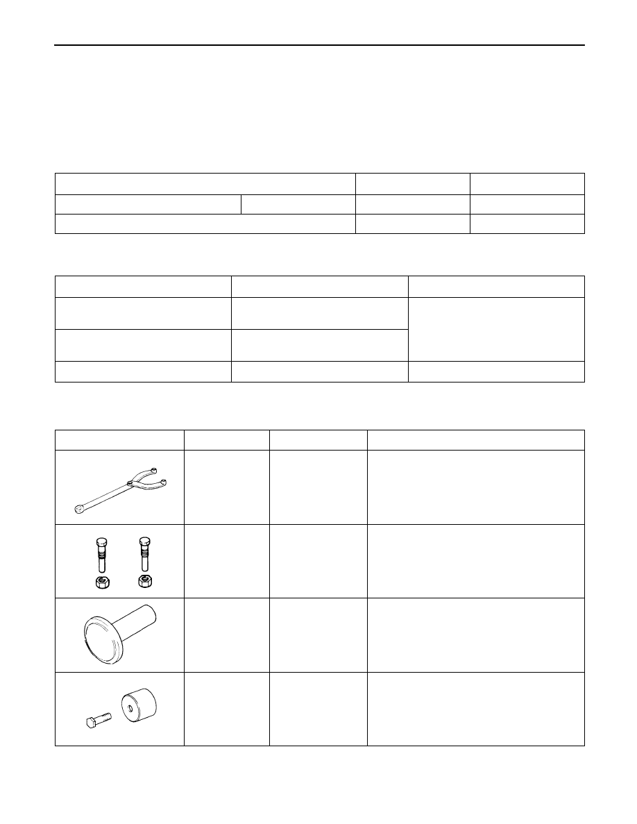
SPECIAL TOOLS
Tool
Number
Name
Use
MB990767
End yoke holder
Holding the camshaft sprocket
MD998719
Crankshaft pulley
holder pin
Holding the camshaft sprocket
MD998762
Circular packing
installer
Press-fitting the circular packing
MD998713
Camshaft oil seal
installer
Press-fitting the camshaft oil seal