Mitsubishi Lancer. Manual - part 204


  Index      Mitsubishi     Mitsubishi Lancer - service repair manual 2006 year


Search            


Content   ..  202  203  204  205   ..


Mitsubishi Lancer. Manual - part 204


CHARGING SYSTEM

ENGINE ELECTRICAL

16-8

If the voltage is not within the standard value, 
there is a malfunction of the voltage regulator or of 
the alternator.

14.After the test, lower the engine speed to the idle 

speed.

15.Turn the ignition switch to the "LOCK" (OFF) 

position.

16.Remove the tachometer or the M.U.T.-II/III.

17.Disconnect the negative battery cable.
18.Disconnect the ammeter and voltmeter.
19.Connect the alternator output wire to the 

alternator "B" terminal.

20.Remove the special tool, and return the connector 

to the original condition.

21.Connect the negative battery cable.

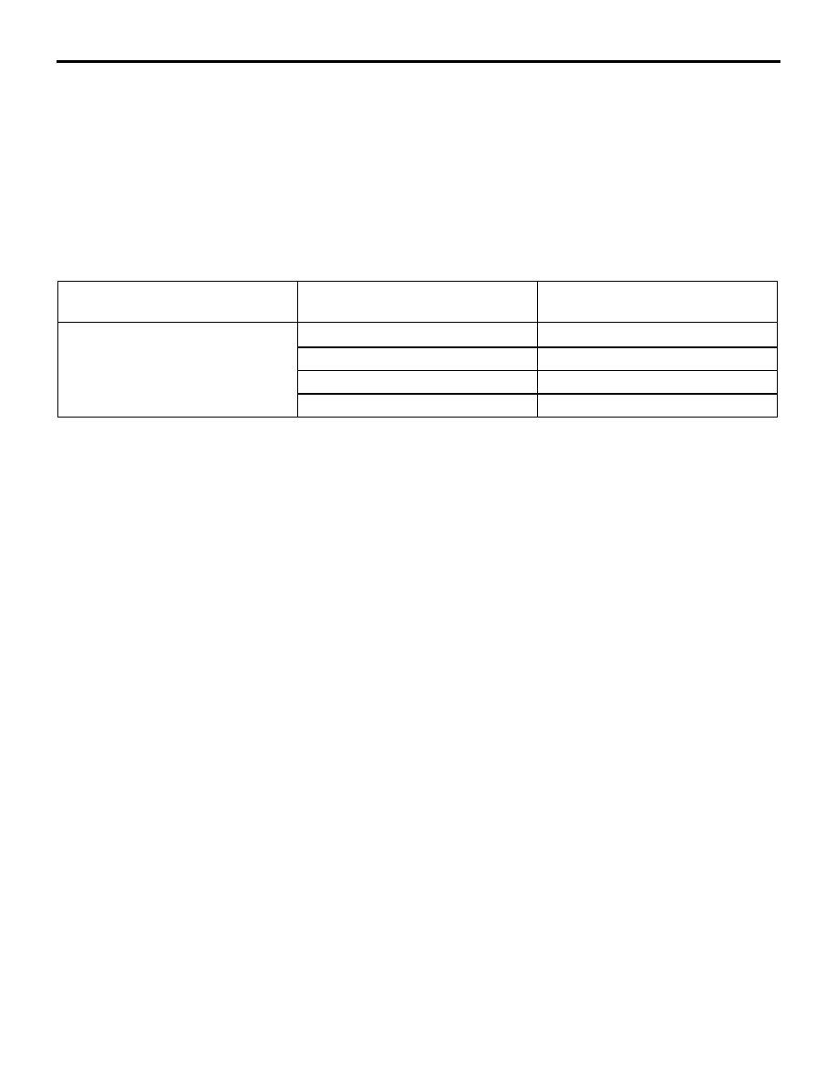
Voltage Regulation Table

Standard value:

Inspection terminal

Voltage regulator ambient 
temperature 

° C

Voltage V

Terminal "S"

−20

14.2 

− 15.4

20

13.9 

− 14.9

60

13.4 

− 14.6

80

13.1 

− 14.5

CHARGING SYSTEM

ENGINE ELECTRICAL

16-9

WAVEFORM CHECK USING AN OSCILLOSCOPE

M1161001200124

MEASUREMENT METHOD

AK100002

Alternator

"B" terminal

CH1

AC

Connect the oscilloscope special patterns pick-up to 
the alternator "B" terminal.

STANDARD WAVEFORM

Observation Conditions

Function

Special pattern

Pattern height

Variable

Variable knob

Adjust while viewing the waveform.

Pattern selector

Raster

Engine speed

Curb idle speed

AKX00189

0.4

(V)

0.2

  0

–0.2

–0.4

Voltage at
alternator
"B" terminal

Time

AG

NOTE: 

AKX00190

The voltage waveform of the alternator "B" terminal 
can undulate as shown in the illustration. This wave-
form is produced when the regulator operates 
according to fluctuations in the alternator load (cur-

rent), and is normal for the alternator. In addition, 
when the voltage waveform reaches an excessively 
high value (approximately 2 V or higher at idle), it 
often indicates an open circuit due to a brown fuse 
between alternator "B" terminal and battery, but not a 
defective alternator.

CHARGING SYSTEM

ENGINE ELECTRICAL

16-10

EXAMPLE OF ABNORMAL WAVEFORMS

NOTE: 

.

1. The size of the waveform patterns differs largely, depending on the adjustment of the variable knob on the 

oscilloscope.

2. Identification of abnormal waveforms is easier when there is a large output current (regulator is not oper-

ating). (Waveforms can be observed when the headlamps are illuminated.)

3. Check the conditions of the charging warning lamp (illuminated/not illuminated). Also, check the charging 

system totally.

Abnormal waveform

Problem cause

Example 1 

AKX00191

Open diode

Example 2 

AKX00192

Short in diode

CHARGING SYSTEM

ENGINE ELECTRICAL

16-11

Example 3 

AKX00193

Broken wire in 
stator coil

Example 4 

AKX00194

Short in stator 
coil

Example 5 

AKX00195

At this time, the charging warning lamp is illuminated.

Open 
supplementary 
diode

Abnormal waveform

Problem cause


Content   ..  202  203  204  205   ..