Mitsubishi Lancer. Manual - part 198


  Index      Mitsubishi     Mitsubishi Lancer - service repair manual 2006 year


Search            


Content   ..  196  197  198  199   ..


Mitsubishi Lancer. Manual - part 198


POWER STEERING HOSES

POWER STEERING

37-40

POWER STEERING HOSES

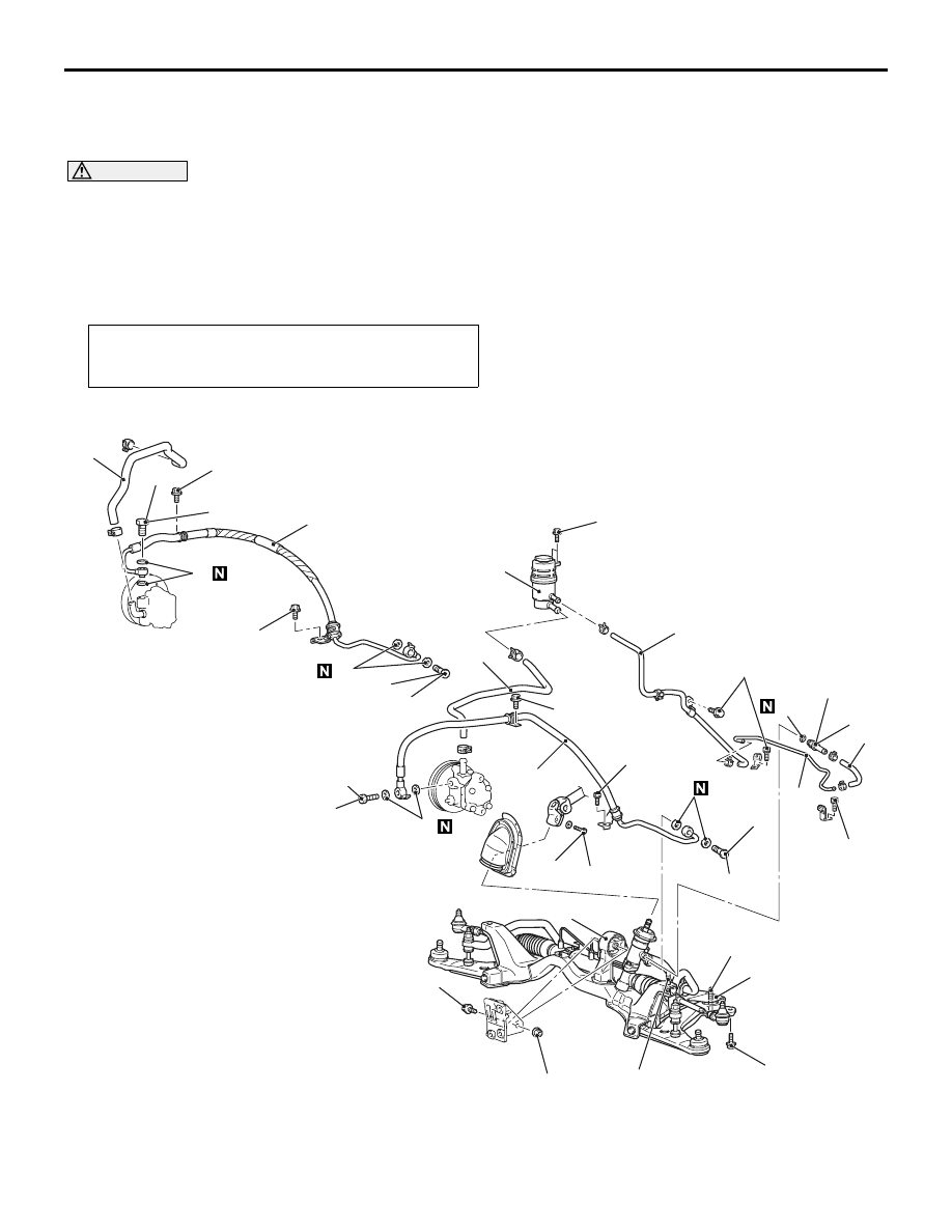
REMOVAL AND INSTALLATION

M1372005700679

CAUTION

• Before removing the clock spring, refer to GROUP 52B, Service Precautions (

P.52B-5

) and Air Bag 

Module and Clock Spring (

P.52B-194

). Also, put the front wheels in straight-ahead position. Fail-

ure to do so may damage the SRS clock spring and render the SRS air bag inoperative, which 
results serious driver injury.

Pre-removal and Post-installation Operation
• Power Steering Fluid Draining and Refilling (Refer to 

P.37-13

). and Bleeding (Refer to 

P.37-14

).

*

: Indicates parts which should be initially tightened, and then fully tightened after placing the 

vehicle horizontally and loading the full weight of the engine on the vehicle body.

<LH drive vehicles>

AC304699 AB

15 ± 3 N·m

18 ± 2 N·m

167 ± 9 N·m

12 ± 2 N·m

49 ± 10 N·m

12 ± 2 N·m

57 ± 7 N·m*

57 ± 7 N·m

3

1

2

9

13

10

7

11

12

5

6

8

12 ± 2 N·m

12 ± 2 N·m

2

9

4

7

8

7

8

7

8

57 ± 7 N·m

57 ± 7 N·m

57 ± 7 N·m

12 ± 2 N·m

167 ± 9 N·m

Crossmember

12 ± 2 N·m

<1300, 1600>

<2000>

12 ± 2 N·m

Removal steps 

1.

Oil reservoir

>>

C

<< 2.

Suction hose

>>

B

<< 3.

Return hose

Clock spring (Refer to GROUP 52B, 
Air Bag Modules and Clock Spring 

P.52B-194

).

Removal steps (Continued)

POWER STEERING HOSES

POWER STEERING

37-41

<RH drive vehicles>

AC304698AB

15 ± 3 N·m

18 ± 2 N·m

167 ± 9 N·m

12 ± 2 N·m

49 ± 10 N·m

12 ± 2 N·m

57 ± 7 N·m*

3

1

2

9

10

7

5

6

2

4

8

8

57 ± 7 N·m

167 ± 9 N·m

Crossmember

12 ± 2 N·m

<1300, 1600>

<2000>

7

6

57 ± 7 N·m

7

6

57 ± 7 N·m

7

6

57 ± 7 N·m

12 ± 2 N·m

Centermember (Refer to GROUP 32, 
Engine Roll Stopper Centermember 

P.32-7

).

Front exhaust pipe (Refer to GROUP 
15, Exhaust Pipe and Main Muffler 

P.15-10

).

4.

Steering gear and joint connecting bolt

5.

Rear roll stopper connecting bolt

6.

Rear roll stopper (Refer to GROUP 32, 
Engine Roll Stopper Centermember 

P.32-7

).

<<

A

>>

7.

Eye bolt

8.

Gasket

9.

Pressure hose assembly

10.

Return tube

>>

A

<< 11.

Return hose

<<

A

>>

12.

Return tube

13.

O-ring

Removal steps (Continued)

Removal steps 

1.

Oil reservoir

>>

C

<< 2.

Suction hose

>>

B

<< 3.

Return hose

Clock spring (Refer to GROUP 52B, 
Air Bag Modules and Clock Spring 

P.52B-194

).

Centermember (Refer to GROUP 32, 
Engine Roll Stopper Centermember 

P.32-7

).

Front exhaust pipe (Refer to GROUP 
15, Exhaust Pipe and Main Muffler 

P.15-10

).

4.

Steering gear and joint connecting bolt

5.

Rear roll stopper connecting bolt

<<

A

>>

6.

Eye bolt

7.

Gasket

8.

Pressure hose assembly

<<

A

>>

9.

Return tube

10. O-ring

POWER STEERING HOSES

POWER STEERING

37-42

REMOVAL SERVICE POINT
<<A>> EYE BOLT/RETURN TUBE 
REMOVAL

CAUTION

If the joint cover grommet has been removed, 
install it properly as follows.

AC304922 AB

A

B

Joint cover 
grommet

Steering gear

Align the joint cover grommet notch (arrow A) 
with the steering gear lug (arrow B), and then 
install the steering joint cover to the steering 
gear.
1. Loosen the crossmember mounting bolts and 

nuts, and lower the crossmember to a position so 
that the eye bolts or return tube at the steering 
gear side can be removed.
NOTE: In this case, do not remove the crossmem-
ber mounting bolts and nuts.

2. Remove the eye bolts or return tube.

INSTALLATION SERVICE POINTS
>>A<< RETURN HOSE INSTALLATION 
<LH DRIVE VEHICLES>

AC100277AB

Return hose

Install the return hose so that the marking is posi-
tioned as shown in the illustration.

>>B<< RETURN HOSE INSTALLATION

AC305132 AB

Return hose

Return tube

Return hose

<LH drive vehicles>

<RH drive vehicles>

Install the return hose so that the markings are posi-
tioned as shown in the illustration.

>>C<< SUCTION HOSE INSTALLATION

Install the suction hose (oil pump side) so that the 
marking is positioned forward.


Content   ..  196  197  198  199   ..