Mitsubishi Lancer. Manual - part 183


  Index      Mitsubishi     Mitsubishi Lancer - service repair manual 2006 year


Search            


Content   ..  181  182  183  184   ..


Mitsubishi Lancer. Manual - part 183


FRONT AXLE HUB ASSEMBLY

FRONT AXLE

26-10

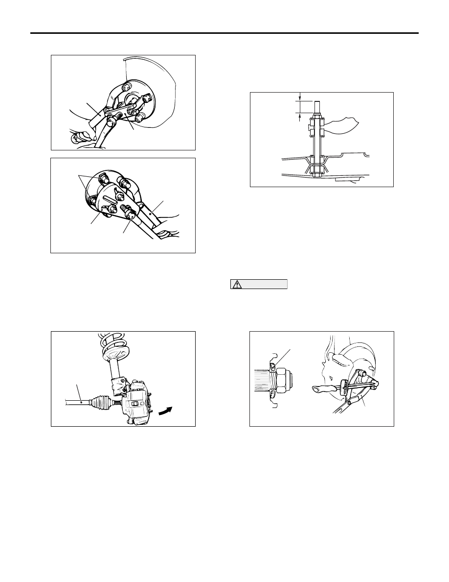
<<E>> DRIVESHAFT REMOVAL

AC100128

MB990241

MB990767

AG

<Invite>

AC303949

MB990244
(Three)

<Intense>

MB990767

MB990242

MB991354

AF

1. Use the following special tools to push out the 

driveshaft from the hub and knuckle.

• Axle shaft puller (MB990241)

• Puller shaft (MB990242)

• Puller bar (MB990244)

• Puller body (MB991354)

AC102551AC

Driveshaft

Front hub and end yoke holder (MB990767)

2. Withdraw the driveshaft from the hub by pulling 

the bottom of the hub and knuckle towards you.

3. Hang the driveshaft on the vehicle body with a 

rope.

INSTALLATION SERVICE POINT
>>A<< STABILIZER RUB-
BER/SELF-LOCKING NUT (STABILIZER 
BAR CONNECTION) INSTALLATION

AC210393AC

A

Install the stabilizer rubber and collar as shown in the 
figure, and tighten the self-locking nut so that the 
protruding length of the stabilizer  bar mounting bolt 
protruding part meets its standard value (A).

Standard value (A): 22 

± 1.5 mm

>>B<< WASHER/ DRIVESHAFT NUT 
INSTALLATION

CAUTION

Before securely tightening the driveshaft nuts, 
make sure there is no load on the wheel bear-
ings. Otherwise the wheel bearings will be dam-
aged.

AC102465AD

MB990767

Washer

1. Be sure to install the driveshaft washer in the 

specified direction.

2. Using special tool front hub and end yoke holder 

(MB990767), tighten the driveshaft nut to the 
specified torque.

Tightening torque: 245 

± 29 N⋅ 

FRONT AXLE HUB ASSEMBLY

FRONT AXLE

26-11

INSPECTION

M1261001800242

• Check the hub for cracks and spline for wear.

• Check the knuckle for cracks.

• Check for defective bearing.

NOTE: If the meshing of the wheel bearing outer 

race and the knuckle, or of the wheel bearing 
inner race and the hub, is loose, replace the 
bearing or damaged parts.

DISASSEMBLY AND REASSEMBLY

M1261001900379

AC303659

N

N

4

1

5

3

2

AF

2

<Invite>

<Intense>

Disassembly steps 

1.

Snap ring

<<

A

>>

2.

Hub

3.

Dust cover

<<

B

>>

4.

Wheel bearing

5.

Knuckle
Reassembly steps 

5.

Knuckle

>>

A

<<

4.

Wheel bearing

1.

Snap ring

3.

Dust cover

2.

Hub

>>

B

<<

Hub starting torque check

>>

C

<<

Wheel bearing axial play check

DISASSEMBLY SERVICE POINTS
<<A>> HUB REMOVAL

CAUTION

When the hub has been removed, always replace 
the wheel bearing with a new part because wheel 
bearing frictional surface will be damaged when 
removing the hub.

AC100130

Tighten the nut
with the bolt
secured

MB991056 or
MB991355

MB991017

MB991000

AB

Use the following special tools to pull out the hub 
from the knuckle.

• Knuckle arm bridge (MB991056 or MB991355)

• Front hub remover and Installer (MB991017)

• Spacer (MB991000)

FRONT AXLE HUB ASSEMBLY

FRONT AXLE

26-12

<<B>> WHEEL BEARING REMOVAL

AC102508 AC

Inner race
(outside)

Outer oil seal

1. Crush the oil seal in two places so that the tabs of 

the special tool will be caught on the wheel 
bearing inner race (outside).

CAUTION

When removing the inner race (outside) from the 
hub, be careful not to let the hub drop.

AC102509

MB990810

Inner race
(outside)

AC

2. Remove the wheel bearing inner race (outside) 

from the front hub by using special tool side 
bearing puller (MB990810).

AC102510 AC

MB990938

MB990935

MB991056 or MB991355

Inner race
(outside)

3. Install the inner race (outside) that was removed 

from the hub to the wheel bearing, and then use 
the following special tools to remove the wheel 
bearing.

• Installer bar (MB990938)

• Installer adapter (MB990935)

• Knuckle arm bridge (MB991056 or MB991355)

REASSEMBLY SERVICE POINTS
>>A<< WHEEL BEARING INSTALLATION

1. Fill the wheel bearing with multipurpose grease.
2. Apply a thin coating of multipurpose grease to the 

knuckle and bearing contact surfaces.

CAUTION

Press the outer race when pressing-in the wheel 
bearing. Otherwise the wheel bearing will be 
damaged.

AC102511

MB990883

MB990890

AC

3. Press-in the bearing by using the following special 

tools.

• Rear suspension bushing arbor (MB990883)

• Rear suspension bushing base (MB990890)

>>B<< HUB STARTING TORQUE CHECK

AC210929 AC

MB991000

MB991017

245 ± 29 N·m

Tighten the nut
with the bolt secured

1. Tighten the following special tools to the specified 

torque, and then press-in the hub into the knuckle.

• Front hub remover and installer (MB991017)

• Spacer (MB991000)

2. Rotate the hub in order to seat the bearing.

AC100136

MB990685

MB990326

AB

FRONT AXLE HUB ASSEMBLY

FRONT AXLE

26-13

3. Measure the hub starting torque by using the 

following special tools.

• Torque wrench (MB990685)

• Preload socket (MB990326)

Limit: 1.8 N

⋅ m

4. The starting torque must be within the limit and 

the hub rotation must be smooth.

>>C<< WHEEL BEARING AXIAL PLAY 
CHECK

AC100137

MB991000

MB991017

245 ± 29 N·m

AB

Tighten the nut
with the bolt
secured

1. Measure to determine whether the wheel bearing 

axial play is within the limit or not by using the 
following special tools.

• Front hub remover and installer (MB991017)

• Spacer (MB991000)

Limit: 0.05 mm

2. If the play is not within the limit range while the nut 

is tightened to 245 

± 29 N⋅ m, the bearing, hub 

and/or knuckle have probably not been installed 
correctly. Replace the bearing and re-install.

INSPECTION

M1261002000078

• Check the front hub and brake disc mounting sur-

faces for galling and contamination.

• Check the knuckle inner surface for galling and 

cracks.


Content   ..  181  182  183  184   ..