Mitsubishi Lancer (4A9 engine). Manual - part 313
TROUBLESHOOTING
AUTOMATIC AIR CONDITIONER
55B-6
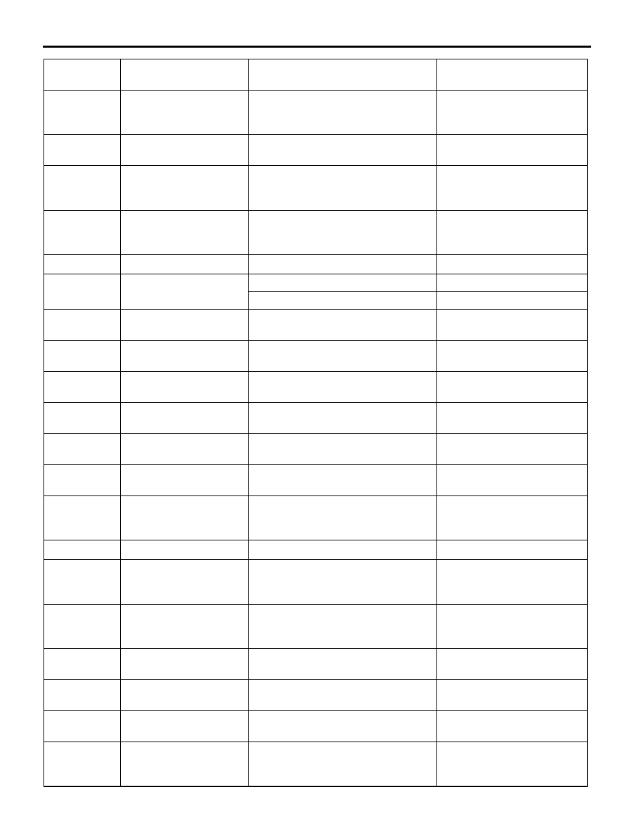
45
In/out select damper
poten (target)
−
Displays outside/inside air
selection damper target
position.
46
In/out select damp
potentiometer
−
Displays outside/inside air
selection damper position.
55
Air outlet c/o
potentiometer
−
Displays air outlet
changeover damper
position.
56
Air outlet c/o potentio.
(Target)
−
Displays air outlet
changeover damper target
position.
57
Low pressure
−
Normal
60
Rear defogger switch
Rear window defogger switch ON
ON
Rear window defogger switch OFF
OFF
61
Pressure sensor
−
Displays refrigerant
pressure.
63
Air mix potentiometer
−
Displays the air mix damper
position.
68
Front blower fan
−
Displays blower motor
condition.
69
Front blower fan
(Target)
−
Displays blower motor target
value.
73
Refrigerant pressure
−
Displays refrigerant
pressure status.
74
Condenser fan
−
Displays condenser fan
running condition.
76
Temp. set dial position
−
Displays the set temperature
output value on the control
panel.
77
A/C Panel type
−
Dial/Auto/RHD
78
Fan set dial position
−
Displays the air volume
output value on the control
panel.
79
Air outlet c/o set dial
position
−
Displays output value to the
air outlet changeover dial on
the control panel.
80
Fan set dial operation
flag
−
ON when the air volume
adjusting dial is operated
81
A/C SW operation flag
−
ON when the air conditioner
switch is operated
82
Temp. set dial operation
flag
−
ON when the air conditioner
switch is operated
83
Defogger flag
−
ON when the air outlet
changeover dial is set to the
DEF position.
Item No.
Check item
Inspection status
The display contents
under normal condition