Mitsubishi Lancer (4A9 engine). Manual - part 309
AC903375
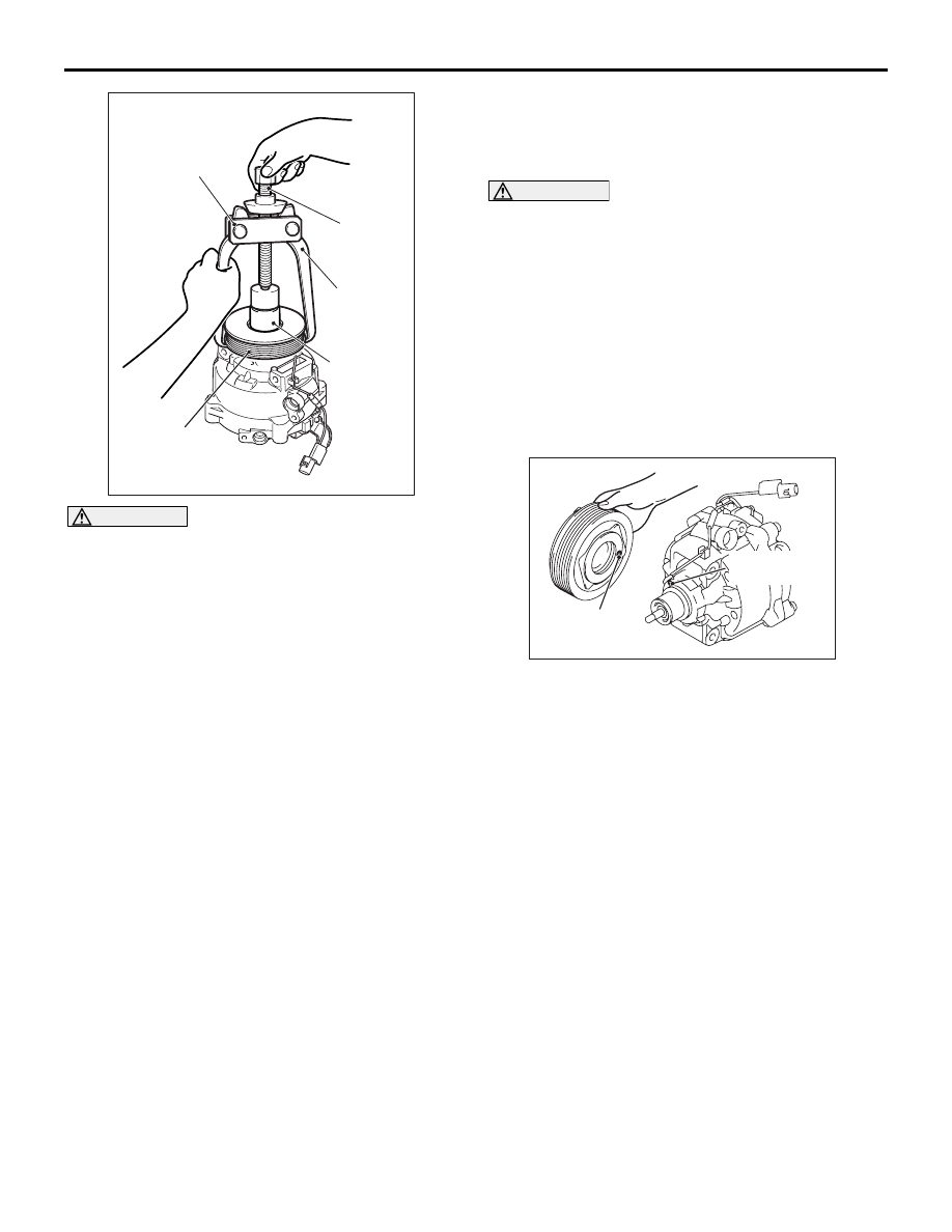
MB992623
AB
Rotor
Threaded
shaft
MB990810
MD999566
COMPRESSOR ASSEMBLY
HEATER, AIR CONDITIONER AND VENTILATION
55A-117
CAUTION
• Be sure to use the guide (MB992623) when
the side bearing puller (MB990810) is used to
prevent the damage of A/C compressor.
• If the threaded shaft of side bearing puller
(MB990810) is turned than necessary, the
rotor may be distorted. Therefore, turn the
threaded shaft lightly only by hand without
using any tools.
Rotor can be removed by hand, but if it is difficult to
remove it, use the guide (MB992623) and the side
bearing puller (MB990810) as shown.
REASSEMBLY SERVICE POINTS
>>A<< A/C COMPRESSOR HIGH PRESSURE
RELIEF VALVE INSTALLATION
CAUTION
Be careful not to damage the O-ring when install-
ing the high-pressure relief valve. Apply the
specified refrigerating machine oil the high-pres-
sure relief valve mounting hole before installa-
tion
Check that O-ring is installed to the high-pressure
relief and use the adjust torque wrench to install the
high-pressure relief valve to the main body of the
compressor.
>>B<< A/C COMPRESSOR COIL ATTACHMENT
AC709545AF
A/C compressor
coil projection
Compressor
unit pin hole
Line up the pin hole on the compressor unit with the
A/C compressor coil projection and attach.